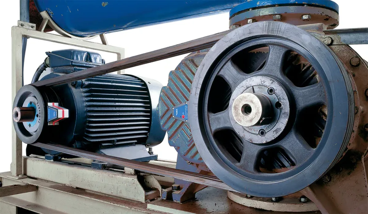
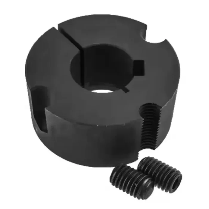
The 5050 taper lock bushing is a key component in power transmission systems, renowned for its versatility and reliability. Our 5050 taper lock bush securely connects shafts to components like pulleys, sprockets, and gears. Its tapered design ensures a tight grip on the shaft, minimizing slippage and maximizing power transmission efficiency. Manufactured with precision engineering and high-quality cast iron materials, the 5050 taper lock bushing offers exceptional durability and resistance to wear and corrosion. Easy to install and remove without damaging the shaft, it provides a cost-effective solution for a wide range of industrial applications, including conveyor systems, agricultural machinery, and industrial equipment.

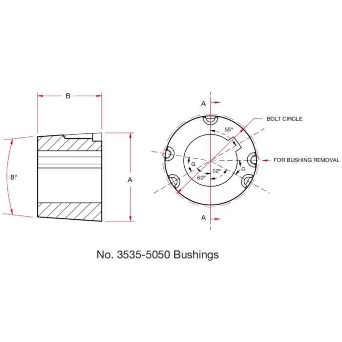
5050 Taper Lock Bushing Dimensions
|
 |
| Bushing Number: | 5050 | |
| Dimensions(in): | A | 7 |
| B | 5 | |
| Bolt Circle: | 6.72 | |
| Installation Screws (UNC): | Thread Dia. (in) | 7/8 |
| Length (in) | 2-1/4 | |
| Stock Bore Range(in): | Min. | 2-5/16 |
| Max. | Standard Keyway 4-1/2 Shallow Keyway 5 |
|
| G: | 37° | |
| Wrench Torque (in-lbs): | 3,100 | |
| Torque Application Capacity(in-lbs): | 126,000 | |
| Approx.Weight(lbs): | 20.9-39.0 | |
Key Features of 5050 Taper Lock Bushings
- High Torque Capacity: 5050 Taper Lock Bushings are designed to handle substantial torque loads, making them ideal for heavy-duty applications like mining, large conveyors, and industrial machinery, ensuring reliable power transmission without slippage.
- Versatile Bore Sizes: These bushings offer a wide range of bore sizes metric and inch, with custom options available, allowing compatibility with various shaft diameters for diverse applications.
- Precision Manufacturing: Crafted from high-grade steel or cast iron, 5050 bushings are precision-engineered for durability, shock load absorption, and consistent performance, reducing wear and extending service life in demanding industrial environments.
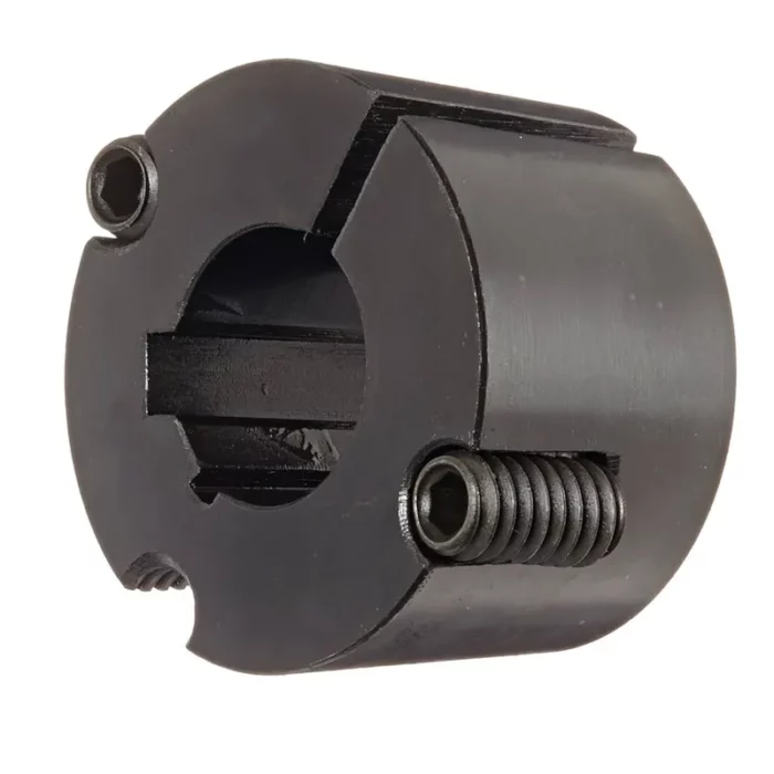
- Easy Installation and Removal: The tapered design with an 8° angle allows for quick, secure installation and removal without shaft damage, minimizing downtime and simplifying maintenance in applications like pulleys, sprockets, and couplings.
- Corrosion Resistance: Available in materials like stainless steel for food-grade or abrasive settings, these bushings feature black oxide coatings or alternative finishes, enhancing resistance to corrosion and ensuring longevity in harsh operating conditions.
- Secure Shaft Grip: The conical outer surface and cylindrical inner bore with H7 tolerance provide a tight, wedging fit, ensuring a firm grip on the shaft, preventing axial displacement, and maintaining alignment during operation.
- Wide Application Range: Used in heavy machinery, aggregate processing, and conveyor systems, these bushings support V-belt, timing, and flat pulleys, sprockets, and couplings, offering flexibility for various industrial power transmission needs.
- Standardized Keyway Design: Featuring standardized keyways, these bushings ensure compatibility with industry-standard components, facilitating easy integration into existing systems while maintaining secure torque transmission and alignment under high loads.
Common Troubleshooting of Taper Lock Bushings
Taper lock bushings are widely used in power transmission systems to secure pulleys, sprockets, or other components to a shaft. Below is a concise guide to common troubleshooting issues with taper lock bushings:
- Bushing Won't Fit on Shaft
- Cause: Incorrect bushing size, burrs on the shaft, or debris in the bushing bore.
- Solution: Verify bushing and shaft dimensions match specifications. Deburr the shaft with fine emery cloth and clean the bushing bore with a solvent-soaked rag. Ensure no keyway obstructions.
- Component Slips on Shaft
- Cause: Insufficient torque on cap screws, worn bushing, or improper installation.
- Solution: Tighten cap screws gradually and evenly in a star pattern to the manufacturer's specified torque (use a torque wrench). Check for bushing or hub wear; replace if damaged. Ensure proper alignment during installation.
- Difficulty Removing Bushing
- Cause: Corrosion, overtightening, or seized screws.
- Solution: Apply penetrating oil to screw threads and bushing interface; let it sit for 10-15 minutes. Insert cap screws into removal holes (if available) and tighten evenly to push the bushing out. Tap lightly with a soft mallet if needed, avoiding damage.
- Vibration or Noise During Operation
- Cause: Loose bushing, misalignment, or unbalanced components.
- Solution: Check screw torque and retighten if necessary. Verify shaft and component alignment using a straightedge or dial indicator. Balance the rotating assembly if required (consult a professional for balancing).
- Cracked or Damaged Bushing
- Cause: Overtightening screws, poor-quality material, or excessive load.
- Solution: Replace the bushing with a high-quality one from a reputable manufacturer. Follow torque specifications exactly. Check system load against design limits to prevent recurrence.
- Keyway or Shaft Damage
- Cause: Improper installation, loose fit, or excessive force.
- Solution: Inspect key and keyway for wear or burrs; replace if damaged. Ensure a snug key fit and proper bushing installation. Avoid forcing the bushing onto the shaft.