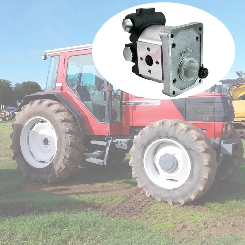
The 5180275 hydraulic gear pump is a robust and reliable component specifically designed for use in FIAT tractors, including the M100, M115, M135, M160, F100, F110, F115, F120, F130, and F140 models. This tractor hydraulic pump plays a crucial role in the hydraulic systems of these tractors, ensuring efficient operation of essential hydraulic functions such as steering, lifting, and other implement controls. It is a precision-engineered device that uses intermeshing gears to create a consistent and pressurized flow of hydraulic fluid, which is essential for the smooth performance of the tractor's hydraulic system.


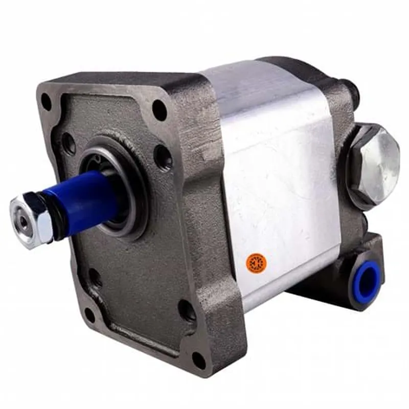
5180275 Hydraulic Gear Pump Specifications
Compatible with FIAT Tractor(s): M100, M115, M135, M160, F100, F110, F115, F120, F130, F140
Compatible with Case IH Tractor(s): JX70U, JX80U, JX90U, JX100U, JX1060C, JX1070C, JX1070U, JX1075C, JX1080U, JX1090U, JX1100U
Compatible with New Holland Tractor(s): TL70, TL80, TL80A, TL90, TL90A, TN55, TN55D, TN55S, TN60A, TN60DA, TN60SA, TN65, TN65D, TN65F, TN65S, TN70, TN70A, TN70D, TN70DA, TN70F, TN70S, TN70SA, TN85F, TN85FA, TN90F, TN95F, TN95FA, 4835, 5635, 6635, 7635, 8160, 8260, 8360
Replacement for Case IH OEM Number(s): 5167394, 5180275
Replacement for New Holland OEM Number(s): 5167394, 5180275
| Applied to: | FIAT Tractor |
| OEM Ref.No.: | 5180275 |
| Nominal Displacement: | 25ml/r |
| Maximum Pressure· | 200bar |
| Rotational Speed: | 500-3000r/min |
| Controlled Flow Rate: | 18L/min |
| Fuel Feed Hole: | Φ20 |
| Fuel Discharge Hole: |
M18*1.5 |
| Direction of Rotation: |
Left (Anti-clockwise) |
Advantages of Tractor Hydraulic Pumps
- High Efficiency in Power Transmission
Tractor hydraulic gear pumps deliver consistent power to hydraulic systems, ensuring efficient operation of implements like loaders or plows. Their simple design minimizes energy loss, providing reliable performance for demanding agricultural tasks, even under heavy loads. - Durable and Robust Construction
These tractor hydraulic pumps are built with sturdy materials like cast iron or aluminum, resisting wear from continuous use. Their robust design withstands harsh conditions, such as dust, heat, and heavy vibrations, ensuring long-lasting performance in rugged farming environments. - Compact and Lightweight Design
Hydraulic gear pumps are compact, making them easy to integrate into tractors without adding significant weight. This design optimizes space, allowing for efficient installation and maintenance while maintaining high performance in confined engine compartments. - Cost-Effective Maintenance and Repairs
Gear pumps have fewer moving parts compared to other hydraulic gear pump types, reducing maintenance costs. Replacement parts are widely available and affordable, and their simple design allows for straightforward repairs, minimizing downtime during critical farming seasons. - Consistent Flow and Pressure
These pumps provide steady hydraulic fluid flow and pressure, ensuring smooth operation of tractor functions like steering and lifting. This consistency enhances precision in tasks, improving productivity and reducing strain on other hydraulic components. - Versatility Across Tractor Models
Hydraulic gear pumps are compatible with various tractor models, such as the FIAT M and F series. Their adaptable design supports multiple applications, from small-scale farming to heavy-duty tasks, making them a versatile choice for diverse agricultural needs.
How Does a Tractor Hydraulic Gear Pump Work?
A tractor hydraulic gear pump is a critical component in a tractor's hydraulic system, responsible for generating the hydraulic pressure required to power various functions such as steering, lifting implements, and operating auxiliary attachments. The working principle of a hydraulic gear pump is based on the movement of fluid through interlocking gears that create pressure and flow.
The tractor hydraulic pump consists of two main components: the driving gear and the driven gear, housed within a precision-machined casing. The driving gear is connected to the tractor's engine or power take-off (PTO). When the tractor is in operation, the engine drives the gears in the pump, causing them to rotate. As the gears rotate, they create a vacuum at the pump's inlet, which draws hydraulic fluid from the reservoir into the pump.
Once inside the hydraulic pump in tractor, the fluid flows around the outer edges of the gears within the casing. As the gears continue to turn, they trap the fluid in the spaces between the gear teeth and the casing. This movement pushes the fluid toward the pump's outlet, where the meshing of the gear teeth prevents backflow, ensuring a consistent and pressurized flow.
The pressurized hydraulic fluid is then delivered to the system's hydraulic cylinders, valves, or motors, enabling various tractor functions. The hydraulic gear pump operates in a continuous loop, drawing fluid from the reservoir, pressurizing it, and circulating it back. Its simple design, with minimal moving parts, ensures efficiency, reliability, and ease of maintenance, making it ideal for agricultural applications where durability and performance are essential.