041683T2 Hydraulic Gear Pump for Massey Ferguson Tractor 297, 299, 465, 475, 630, 650
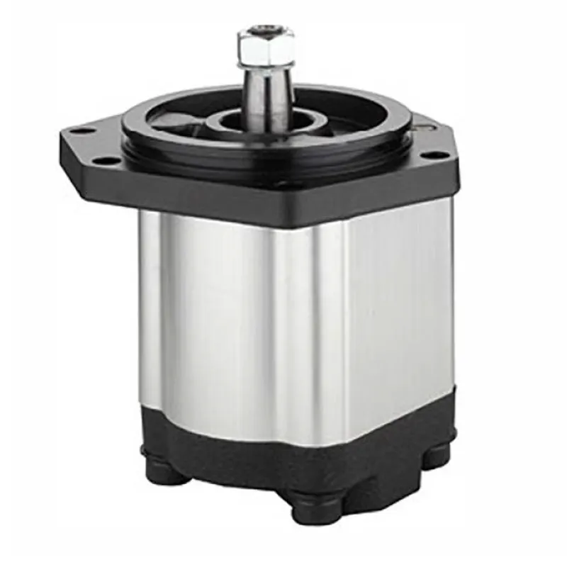
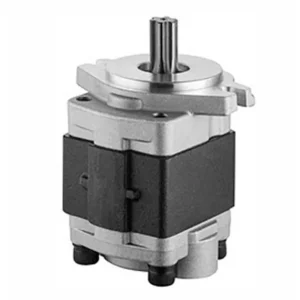
The 041683T2 Hydraulic Gear Pump is a critical replacement component designed for Massey Ferguson tractors, specifically models 297, 299, 465, 475, 630, and 650. This pump powers the tractor’s hydraulic system, supplying pressurized fluid to operate implements like loaders, backhoes, and steering systems. It replaces OEM part numbers 041682T1, 041683T1, 041683T2, 9510080761, and A67501, ensuring compatibility and reliable performance. This tractor hydraulic pump plays a critical role in the tractor’s hydraulic system, facilitating the flow of hydraulic fluid to power essential functions such as lifting, steering, and operating auxiliary implements.
The 041683T2 Hydraulic Gear Pump is a critical replacement component designed for Massey Ferguson tractors, specifically models 297, 299, 465, 475, 630, and 650. This pump powers the tractor’s hydraulic system, supplying pressurized fluid to operate implements like loaders, backhoes, and steering systems. It replaces OEM part numbers 041682T1, 041683T1, 041683T2, 9510080761, and A67501, ensuring compatibility and reliable performance. This tractor hydraulic pump plays a critical role in the tractor's hydraulic system, facilitating the flow of hydraulic fluid to power essential functions such as lifting, steering, and operating auxiliary implements.
041683T2 Hydraulic Gear Pump Specifications
Compatible with Massey Ferguson Tractor(s): 297, 299, 465, 475, 630, 650
Replacement for Massey Ferguson OEM Number(s): 041682T1, 041683T1, 041683T2, 9510080761, A67501
| Applied to: | Massey Ferguson Tractor |
| OEM Ref.No.: | 041682T1, 041683T2 |
| Nominal Displacement: | 22ml/r |
| Maximum Pressure· | 250bar |
| Rotational Speed: | 250-2500r/min |
| Fuel Feed Hole: | G1 |
| Fuel Discharge Hole: | 7/8 24UNF 2B |
| Direction of Rotation: | Rght(Clockwise) |
Tractor Hydraulic Gear Pump Parts
- Pump Housing
The pump housing is a robust cast iron or aluminum enclosure that encases all internal components. It provides structural integrity, protects gears from external debris, and ensures proper alignment for efficient operation. Designed to withstand high hydraulic pressures, it includes mounting flanges for secure tractor installation. - Drive Gear
The drive gear is a precision-machined component connected to the tractor’s power source, typically the engine or PTO shaft. It rotates to mesh with the driven gear, creating fluid movement. Made from hardened steel, it ensures durability and consistent performance under heavy loads. - Driven Gear
The driven gear works in tandem with the drive gear, rotating in the opposite direction to displace hydraulic fluid. Its precise tooth design minimizes wear and ensures smooth operation. Constructed from high-strength materials, it maintains efficiency in demanding agricultural tasks. - Inlet and Outlet Ports
These ports facilitate the flow of hydraulic fluid into and out of the tractor hydraulic gear pump. The inlet draws fluid from the reservoir, while the outlet directs pressurized fluid to the tractor’s hydraulic system. Machined for leak-proof connections, they ensure reliable fluid transfer. - Seals and Gaskets
Seals and gaskets prevent fluid leaks and maintain internal pressure. Made from durable rubber or synthetic materials, they resist oil degradation and high temperatures. Properly fitted seals ensure the tractor hydraulic pump operates efficiently, reducing maintenance needs and extending component lifespan. - Bearings or Bushings
Bearings or bushings support the rotating gears, reducing friction and wear. Typically made from bronze or steel, they ensure smooth gear movement and prolong the hydraulic pump for tractor life. High-quality bearings enhance efficiency, minimizing energy loss during hydraulic fluid displacement.
How to Replace Hydraulic Pump on Tractor
- Prepare the Tractor
Park the tractor on a flat surface and engage the parking brake. Turn off the engine and disconnect the battery to ensure safety. Lower any attached implements to relieve hydraulic pressure. Gather tools like wrenches, sockets, and a drain pan for fluid collection. - Drain Hydraulic Fluid
Locate the hydraulic reservoir and place a drain pan underneath. Remove the drain plug or open the valve to drain the fluid completely. This prevents spills and contamination during tractor hydraulic pump removal. Dispose of old fluid according to local regulations. - Access the Pump
Remove any panels, guards, or components obstructing access to the hydraulic gear pump. Identify the pump’s location, typically near the engine or transmission. Take note of hose connections and mounting bolts for accurate reassembly. Label hoses if necessary to avoid confusion. - Remove the Old Pump
Disconnect hydraulic hoses from the pump’s inlet and outlet ports, capping them to prevent contamination. Unbolt the pump from its mounting bracket using appropriate tools. Carefully remove the hydraulic pump from tractor, inspecting the drive gear or coupling for wear or damage. - Install the New Pump
Position the new hydraulic gear pump in the mounting bracket. Align the drive gear or coupling properly. Secure the pump with bolts, tightening them to the manufacturer’s torque specifications. Reconnect hydraulic hoses to the correct ports. - Refill and Test
Reinstall the drain plug and refill the hydraulic reservoir with the recommended fluid type. Reconnect the battery and start the tractor. Check for leaks around the tractor hydraulic gear pump and test hydraulic functions. Top off fluid if needed and replace any removed panels.

Additional information
| Edited by | Yjx |
|---|
Related products
-
D8NN600AC Hydraulic Gear Pump for Ford Tractor 5110, 5610, 6410, 6610, 6710, 6810, 7010, 7410, 7610, 7710, 7810, 7910, 8010, 8210
-

D8NN600KB Hydraulic Gear Pump for Ford Tractor 5600, 6600, 6700, 7600, 7700
-
D8NN600FA Hydraulic Gear Pump for Ford Tractor 8200 8400 8600 9200 9600 9700
-
CPC30.5.18 Forklift Hydraulic Pumps
-

2CB-E8.8/2.1 Log Splitter Hydraulic Pump 2 Stage Log Splitter Pumps