3030 Taper Lock Bushings
The 3030 taper lock bushing is a key component in power transmission systems, renowned for its versatility and reliability. Our 3030 taper lock bush securely connects shafts to components like pulleys, sprockets, and gears. Its tapered design ensures a tight grip on the shaft, minimizing slippage and maximizing power transmission efficiency. Manufactured with precision engineering and high-quality cast iron materials, the 3030 taper lock bushing offers exceptional durability and resistance to wear and corrosion.
The 3030 taper lock bushing is a key component in power transmission systems, renowned for its versatility and reliability. Our 3030 taper lock bush securely connects shafts to components like pulleys, sprockets, and gears. Its tapered design ensures a tight grip on the shaft, minimizing slippage and maximizing power transmission efficiency. Manufactured with precision engineering and high-quality cast iron materials, the 3030 taper lock bushing offers exceptional durability and resistance to wear and corrosion. Easy to install and remove without damaging the shaft, it provides a cost-effective solution for a wide range of industrial applications, including conveyor systems, agricultural machinery, and industrial equipment.
3030 Taper Lock Bushing Dimensions
| 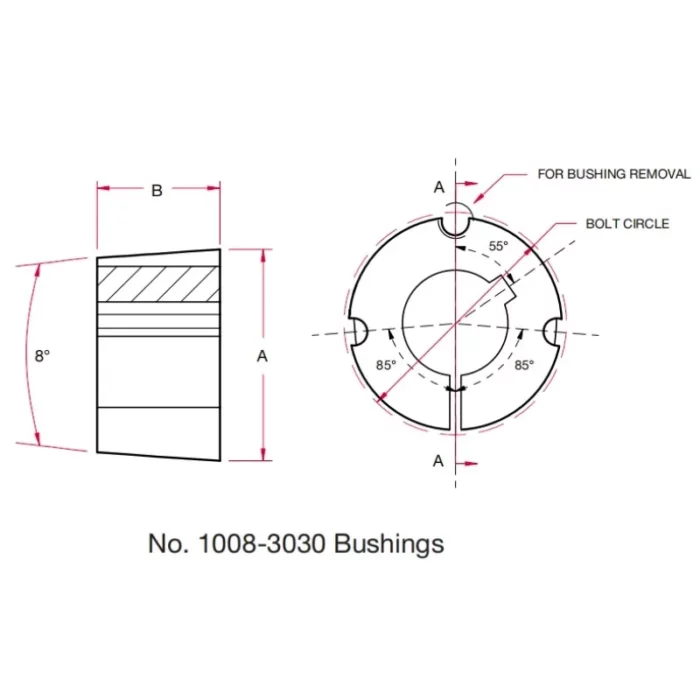 |
| Bushing Number: | 3030 | |
| Dimensions(in): | A | 4-1/4 |
| B | 3 | |
| Bolt Circle: | 4 | |
| Installation Screws (UNC): | Thread Dia. (in) | 5/8 |
| Length (in) | 1-1/4 | |
| Stock Bore Range(in): | Min. | 15/16 |
| Max. | Standard Keyway 2-3/4 Shallow Keyway 3 | |
| Wrench Torque (in-lbs): | 800 | |
| Torque Application Capacity(in-lbs): | 24,000 | |
| Approx.Weight(lbs): | 6.4-10.0 | |
Materials of 3030 Taper Lock Bushings
3030 Taper Lock Bushings are commonly made from the following materials, each chosen for specific properties that enhance performance, durability, and compatibility with various industrial applications:
- Steel: Steel is a primary material for 3030 Taper Lock Bushings due to its high strength and durability. It provides excellent resistance to wear and deformation under heavy loads, making it ideal for demanding industrial environments like automotive and construction machinery. Steel bushings are often coated with black oxide to enhance corrosion resistance, ensuring longevity in applications requiring secure shaft connections.
- Stainless Steel: Stainless steel is used for 3030 Taper Lock Bushings in applications requiring superior corrosion resistance. Its ability to resist rust and chemical degradation makes it suitable for harsh environments, such as food processing or marine settings. Stainless steel maintains structural integrity under high torque, offering reliable performance where hygiene and durability are critical.
- Cast Iron: Cast iron, often GG25 grade, is another common material for these bushings, valued for its machinability and cost-effectiveness. It provides a robust shrink-on fit for uniform load applications, like pulleys and sprockets. Cast iron’s durability supports heavy-duty uses in agriculture and manufacturing, though it’s less resistant to corrosion than stainless steel.
- Ductile Iron: Ductile iron is occasionally used for its enhanced toughness and flexibility compared to standard cast iron. It resists cracking under stress, making it suitable for dynamic applications with high shock loads. Ductile iron bushings offer a balance of strength and cost, often employed in industrial machinery requiring reliable, long-term performance.
Taper Lock Bushing Install and Remove
Install Taper Lock Bushing
(1) Thoroughly clean the shaft, bushing bore, exterior of the bushing, and sprocket/sheave hub bore to remove any traces of oil, paint, or dirt. Additionally, carefully file away any burrs for smooth and precise assembly.
(2) Insert the bushing into the sprocket/sheave hub and align the holes. All holes should be half-threaded, with installation holes threaded on the sprocket side and removal holes threaded on the bushing side. See Figure 1 below.
(3) Apply a light coating of oil to the bolts and thread them into the half-threaded installation holes, as indicated by the white installation holes in Figure 1.
(4) Position the sprocket/sheave and bushing assembly onto the shaft, ensuring the key rests in the shaft keyway. Allow for slight axial movement of the sprocket/sheave, which may occur during the tightening process.
(5) Alternatively, apply torque to the bushing bolts until the sprocket/sheave and bushing tapers are fully seated together. Use approximately half of the recommended bolt torque.
(6) Inspect the alignment and axial runout (wobble) of the sprocket/sheave, and make adjustments as required for proper alignment.
(7) Continue alternating the tightening of the bolts until reaching the recommended torque values specified in Table 1 above.
(8) To enhance the bushing's gripping force, firmly tap the face of the bushing using a brass drift or punch. Avoid hitting the bushing directly with the hammer.
(9) Re-torque the bushing bolts after completing Step 8. Once the recommended bolt torque value is reached, do not continue tightening. Over-tightening may lead to over-insertion of the bushing.
(10) After the initial drive run-in, recheck all bolt torque values and periodically thereafter. If any bolts are found to be loose, repeat steps 5 through 9.

Figure 1
Remove the Taper Lock Bushing
(1) Begin by loosening and removing all mounting bolts.
(2) Insert bolts into all jack screw holes, as indicated by the dark removal holes in Figure 1.
(3) Loosen the bushing by alternately tightening the bolts in small, equal increments until the tapered sprocket/sheave and bushing surfaces disengage.
Additional information
| Edited by | Yjx |
|---|