Disc-O-Flex Couplings
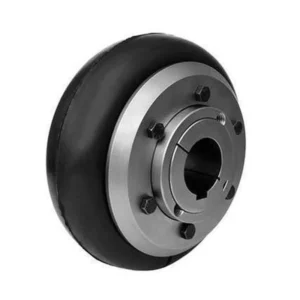
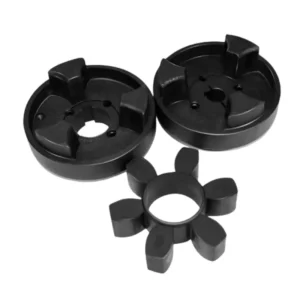
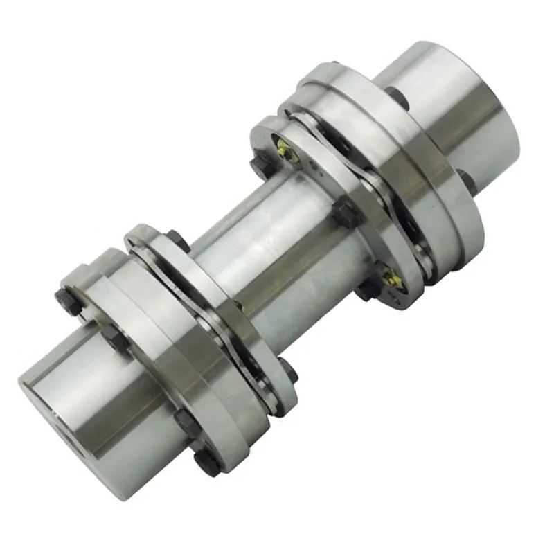
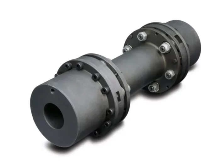
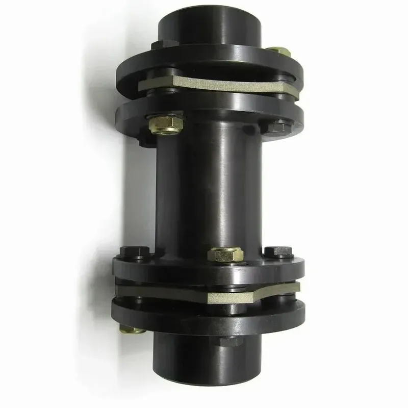
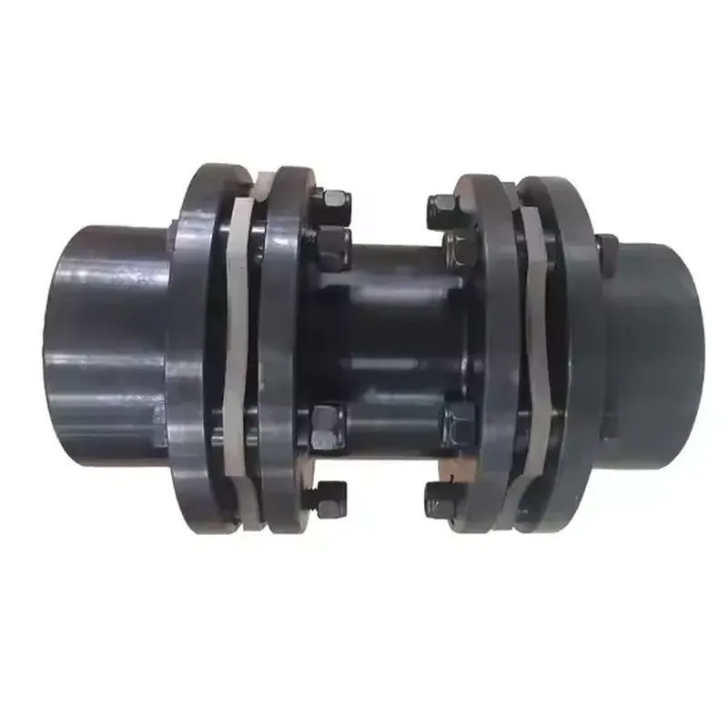
The Disc-O-Flex Coupling is a fully metallic, high-performance flexible coupling designed to transmit torque while accommodating shaft misalignment in industrial applications. It typically consists of two hubs, a center spacer, and two sets of stainless steel disc packs, bolted together with high-tensile bolts. The disc packs, composed of thin, flexible stainless steel blades, allow the coupling to compensate for angular, parallel, and axial misalignment between connected shafts, minimizing stress on equipment. Known for its torsionally rigid design, it delivers reliable torque transmission without backlash, requires no lubrication, and offers excellent durability. It’s widely used in industries like petroleum, manufacturing, and power transmission for its corrosion resistance and precision.
The Disc-O-Flex Coupling is a fully metallic, high-performance flexible coupling designed to transmit torque while accommodating shaft misalignment in industrial applications. It typically consists of two hubs, a center spacer, and two sets of stainless steel disc packs, bolted together with high-tensile bolts. The disc packs, composed of thin, flexible stainless steel blades, allow the coupling to compensate for angular, parallel, and axial misalignment between connected shafts, minimizing stress on equipment. Known for its torsionally rigid design, it delivers reliable torque transmission without backlash, requires no lubrication, and offers excellent durability. It’s widely used in industries like petroleum, manufacturing, and power transmission for its corrosion resistance and precision.
Disc Couplings Size Chart
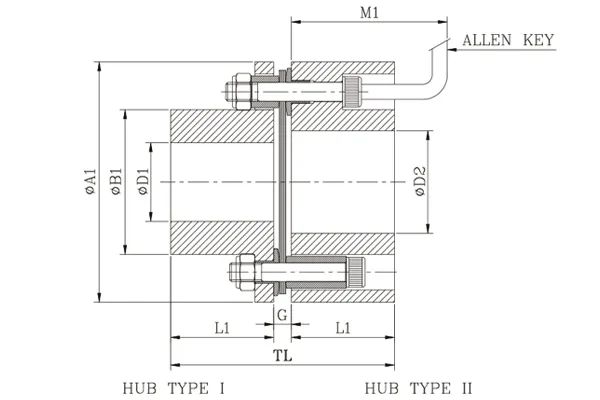
NE Type Disc-O-Flex Couplings
 | 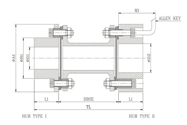 |
| Size | Kw @100 RPM | Torque Nm | Max Speed rpm | Bore | Min. DBSE 'S' | ØA1 | ØB1 | L1 | Std. DBSE | TL (Std. DBSE) | * M1 | Weight in kg. Approx. | M. 1.(WR² ),_ in kgm² Approx. | Tors. Stiff. MNm/ rad Approx. | ||||
| Min ØD1 & Ø02 | Max. | |||||||||||||||||
| Ø01 Type I | Ø02 Type II | Min. Std. `S' | Per Mtr Extra `S' | Min. Std. `S' | Per Mtr Extra 'S' | |||||||||||||
| 5 | 0.35 | 33 | 7500 | 8 | 20 | 22 | 41 | 55 | 30 | 25 | 100 140 | 150 190 | 65 | 0.81 | 2.03 | 0.0003 | 0.0003 | 0.016 |
| 10 | 0.67 | 64 | 7500 | 10 | 22 | 25 | 55 | 63 | 35 | 30 | 160, 200 | 75 | 1.37 | 2.29 | 0.0006 | 0.0004 | 0.031 | |
| 35 | 1.67 | 159 | 7000 | 12 | 30 | 38 | 57 | 82 | 45 | 40 | 100 140 180 | 180,220 260 | 85 | 2.49 | 3.19 | 0.0021 | 0.0011 | 0.025 |
| 95 | 5.4 | 516 | 6000 | 17 | 40 | 50 | 82 | 102 | 57 | 45 | 1920, 230, 270 | 95 | 4.93 | 6.01 | 0.006 | 0.0017 | 0.040 | |
| 170 | 9.0 | 859 | 5200 | 17 | 52 | 70 | 89 | 128 | 77 | 55 | 210, 250, 290 | 110 | 8.48 | 6.98 | 0.018 | 0.0047 | 0.099 | |
| 220 | 14.0 | 1337 | 4800 | 22 | 65 | 80 | 108 | 146 | 94 | 60 | 140 | 260, 300 | 120 | 12.45 | 8.38 | 0.035 | 0.0088 | 0.176 |
| 400 | 25.0 | 2387 | 4400 | 27 | 80 | 100 | 114 | 176 | 115 | 70 | 180 | 280, 320 | 140 | 20.63 | 13.08 | 0.09 | 0.021 | 0.305 |
| 520 | 35.0 | 3342 | 4200 | 32 | 90 | 115 | 126 | 197 | 132 | 90 | 180 | 360, 430 | 175 | 32.01 | 21.72 | 0.17 | 0.056 | 0.432 |
| 1000 | 53.0 | 5061 | 4000 | 42 | 105 | 130 | 143 | 225 | 147 | 95 | 250 | 370, 440 | 185 | 37.09 | 21.72 | 0.25 | 0.056 | 0.600 |
| 1300 | 75.0 | 7162 | 3800 | 47 | 115 | 140 | 168 | 250 | 162 | 105 | 180 250 300 | 390, 460, 510 | 195 | 64.92 | 27.06 | 0.53 | 0.067 | 0.800 |
| 2000 | 105.0 | 10027 | 3700 | 52 | 120 | 155 | 180 | 275 | 178 | 115 | 410, 480, 530 | 215 | 86.97 | 42.79 | 0.86 | 0.167 | 1.130 | |
| 2500 | 140.0 | 13369 | 3600 | 62 | 135 | 165 | 180 | 300 | 190 | 130 | 440, 510, 560 | 2s35 | 114.42 | 42.79 | 1.35 | 0.167 | 1.520 | |
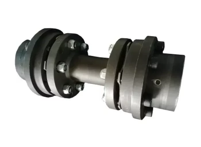
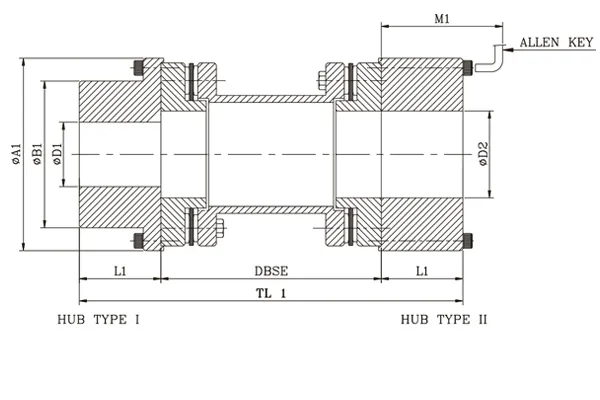
NEK Type Disc-O-Flex Couplings
 |  |
| Size | kW at 100 rpm | Torque Nm | Max Speed rpm | Bore | ØA1 | ØB1 | L1 | DBSE G | TL | * M1 | Weight in kg. (Approx.) | M.I.(WR²) in kgm²(Approx.) | Torsional Stiffness MNm/Rad (Approx.) | ||
| Min. ØD1 & ØD2 | Max. | ||||||||||||||
| ØD1 (Type I) | ØD2 (Type II) | ||||||||||||||
| 5 | 0.35 | 33 | 7500 | 8 | 20 | 22 | 55 | 30 | 25 | 5.2 | 55.2 | 65 | 0.63 | 0.0012 | 0.036 |
| 10 | 0.67 | 64 | 7500 | 10 | 24 | 25 | 63 | 35 | 30 | 6.5 | 66.5 | 75 | 0.97 | 0.0019 | 0.043 |
| 35 | 1.67 | 159 | 7000 | 12 | 30 | 38 | 82 | 45 | 40 | 6.5 | 86.5 | 85 | 1.94 | 0.0036 | 0.062 |
| 95 | 5.4 | 516 | 6000 | 17 | 40 | 50 | 102 | 57 | 45 | 8.0 | 98 | 95 | 3.42 | 0.0082 | 0.118 |
| 170 | 9.0 | 859 | 5200 | 17 | 52 | 70 | 128 | 77 | 55 | 9.5 | 119.5 | 110 | 6.02 | 0.0177 | 0.260 |
| 220 | 14.0 | 1337 | 4800 | 22 | 65 | 80 | 146 | 94 | 60 | 12.0 | 132 | 120 | 8.63 | 0.0308 | 0.492 |
| 400 | 25.0 | 2387 | 4400 | 27 | 80 | 100 | 176 | 115 | 70 | 13.0 | 153 | 140 | 14.24 | 0.0700 | 1.228 |
| 520 | 35.0 | 3342 | 4200 | 32 | 90 | 115 | 197 | 132 | 90 | 14.4 | 194.4 | 175 | 22.21 | 0.1320 | 1.926 |
| 1000 | 53.0 | 5061 | 4000 | 42 | 105 | 130 | 225 | 147 | 95 | 16.2 | 206.2 | 185 | 30.62 | 0.2367 | 3.613 |
| 1300 | 75.0 | 7162 | 3800 | 47 | 115 | 140 | 250 | 162 | 105 | 19.5 | 229.5 | 195 | 42.70 | 0.3990 | ON REQUEST |
| 2000 | 105.0 | 10027 | 3700 | 52 | 120 | 155 | 275 | 178 | 115 | 21.5 | 251.5 | 215 | 57.30 | 0.6350 | |
| 2500 | 140.0 | 13369 | 3600 | 62 | 135 | 165 | 300 | 190 | 130 | 23.5 | 283.5 | 235 | 75.62 | 0.9976 | |
BH Type Disc-O-Flex Couplings
 |  | 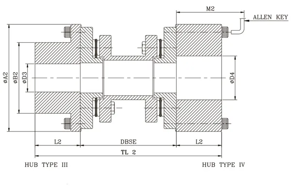 |
| Coup. Size | kW at 100 rpm | Tor- que Nm | Max Speed rpm | Bore | Min. DBSE 'S' | ØA1 | ØA2 | ØB1 | ØB2 | L1 | L2 | Std. DBSE | M1 | M2 | Weight in kg Approx. | M. I.(WR²) in kgm² Approx. | Tors. Stiff. MNm/ rad Approx. | |||||||
| Min. | Max. | |||||||||||||||||||||||
| ØD1 & ØD2 Type I/II | ØD3 & ØD4 Typo III/IV | ØD1 Type I | ØD2 Type II | ØD3 Type III | ØD4 Type IV | Min. DBSE "S" | Per Mtr Extra 'S' | Min. DBSE "S" | Per Mtr Extra 'S' | |||||||||||||||
| 4 | 0.35 | 33 | 7500 | 8 | 8 | 19 | 32 | 24 | 42 | 51 | 61 | 69 | 32 | 40 | 25 | 30 | 100 140 180 | 70 | 80 | 1.27 | 1.20 | 0.0006 | 0.0001 | 0.016 |
| 8 | 0.67 | 64 | 7500 | 8 | 10 | 24 | 42 | 38 | 48 | 65 | 69 | 90 | 40 | 55 | 30 | 40 | 80 | 90 | 1.95 | 1.32 | 0.0012 | 0.0002 | 0.031 | |
| 25 | 1.67 | 159 | 7000 | 10 | 15 | 38 | 48 | 48 | 72 | 71 | 90 | 108 | 55 | 70 | 40 | 45 | 90 | 105 | 3.65 | 2.29 | 0.0039 | 0.0006 | 0.025 | |
| 65 | 5.4 | 516 | 6000 | 15 | 20 | 48 | 72 | 65 | 92 | 95 | 108 | 135 | 70 | 86 | 45 | 55 | 105 | 120 | 5.92 | 3.19 | 0.0094 | 0.0011 | 0.040 | |
| 125 | 9.0 | 859 | 5200 | 20 | 25 | 65 | 92 | 80 | 102 | 107 | 135 | 152 | 86 | 108 | 55 | 60 | 140 | 120 | 125 | 10.93 | 4.74 | 0.0283 | 0.0034 | 0.095 |
| 165 | 14.0 | 1337 | 4800 | 25 | 30 | 80 | 102 | 90 | 120 | 129 | 152 | 182 | 108 | 130 | 60 | 70 | 180 | 125 | 135 | 17.67 | 8.38 | 0.0604 | 0.0088 | 0.170 |
| 370 | 25.0 | 2387 | 4400 | 30 | 45 | 90 | 120 | 108 | 140 | 142 | 182 | 197 | 130 | 158 | 70 | 90 | 180 250 | 135 | 155 | 28.99 | 13.08 | 0.1410 | 0.0213 | 0.300 |
| 390 | 35.0 | 3342 | 4200 | 45 | 55 | 108 | 140 | 127 | 155 | 153 | 197 | 225 | 158 | 181 | 90 | 95 | 155 | 160 | 51.81 | 21.72 | 0.3650 | 0.0561 | 0.430 | |
| 790 | 53.0 | 5061 | 4000 | 55 | 65 | 127 | 155 | 140 | 178 | 156 | 225 | 250 | 181 | 206 | 95 | 105 | 160 | 170 | 52.88 | 21.72 | 0.4181 | 0.0561 | 0.600 | |
| 1025 | 75.0 | 7162 | 3800 | 65 | 70 | 140 | 178 | 155 | 192 | 169 | 250 | 275 | 206 | 223 | 105 | 115 | 170 | 190 | 73.37 | 27.06 | 0.7067 | 0.0670 | 0.800 | |
| 1425 | 105.0 | 10027 | 3700 | 70 | 75 | 155 | 192 | 170 | 212 | 188 | 275 | 300 | 223 | 248 | 115 | 130 | 250 | 190 | 215 | 97.28 | 42.79 | 1.1340 | 0.1666 | 1.100 |
| 1880 | 140.0 | 13369 | 3600 | 75 | 80 | 170 | 212 | 190 | 255 | 202 | 300 | 375 | 248 | 280 | 130 | 145 | 215 | 245 | 127.37 | 42.79 | 1.7740 | 0.1666 | 1.500 | |
Key Features of Disc-O-Flex Couplings
Disc-O-Flex couplings, as a type of flexible disc coupling, offer several key features that make them suitable for various industrial applications. Based on general knowledge of disc coupling designs and their typical characteristics, here are the key features of Disc-O-Flex couplings:
- High Power-to-Weight Ratio: These couplings are designed to transmit significant torque relative to their lightweight and compact construction, making them efficient for applications where space and weight are considerations.
- No Lubrication Required: Being fully metallic, Disc-O-Flex couplings rely on flexible stainless steel disc packs rather than moving parts that require lubrication, reducing maintenance needs and ensuring long-term reliability.
- Torsional Rigidity: They provide high torsional stiffness, ensuring precise torque transmission with minimal backlash, which is ideal for applications requiring accurate positioning or synchronous operation.
- Misalignment Accommodation: The flexible disc elements allow the coupling to compensate for angular, parallel, and axial misalignments between connected shafts, reducing stress on equipment and extending component life.
- Easy Maintenance and Inspection: The design often includes a "drop-out" spacer, enabling replacement of flexible disc packs without disturbing the driving or driven equipment. Visual inspection is also possible without disassembly, enhancing operational efficiency.
- Durable Construction: Typically featuring stainless steel flexible membranes and high-tensile bolts, these couplings are built to withstand demanding conditions, including high speeds and temperatures, with non-stainless components often coated for corrosion resistance.
- High Speed Capability: The inherent balance and lightweight design make Disc-O-Flex couplings suitable for high rotational speeds, often used in applications like pumps, compressors, or cooling tower drives.
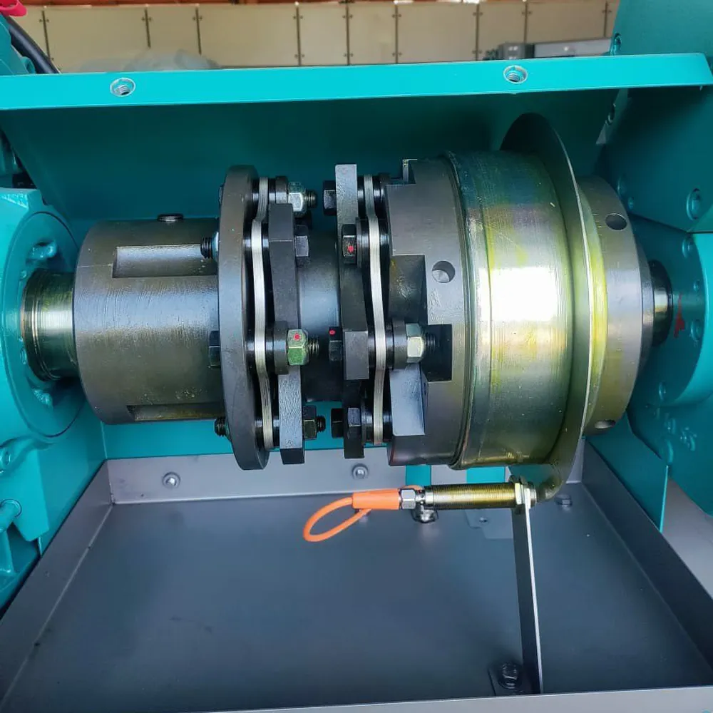
Applications of Flexible Disc Couplings
Flexible disc couplings, also known as disc pack couplings or diaphragm couplings, are mechanical devices used to connect two rotating shafts while accommodating misalignment, transmitting torque, and providing flexibility. They consist of a series of thin, flexible metal discs stacked together, typically made from stainless steel, which allow for angular, parallel, and axial misalignment while maintaining high torsional stiffness. Here are some key applications of flexible disc couplings across various industries:
- Industrial Machinery Power Transmission: Flexible disc couplings are employed in industrial machinery like pumps, compressors, and conveyors to transmit power between shafts. They handle high torque loads while compensating for slight angular, axial, or parallel misalignments, ensuring smooth operation and reducing wear on components.
- Turbine and Generator Systems: In power generation setups, such as gas or steam turbines connected to generators, these couplings provide reliable torque transfer. Their flexibility absorbs vibrations and misalignments caused by thermal expansion or operational stresses, enhancing system longevity and efficiency.
- Precision Equipment in Manufacturing: Flexible disc couplings are ideal for precision applications like CNC machines and robotic arms. They maintain accurate shaft alignment under dynamic conditions, minimizing backlash and ensuring consistent performance in high-speed, high-accuracy manufacturing processes.
- Aerospace and Defense Mechanisms: Used in aerospace systems, such as helicopter rotors or satellite actuators, these couplings withstand extreme conditions. Their lightweight, high-strength design accommodates misalignment from structural flexing or thermal changes while delivering reliable power transmission.
- Automotive Testing and Drivelines: In automotive dynamometers and driveline systems, flexible disc couplings connect engines to test equipment. They handle high rotational speeds and torque variations, absorbing shocks and misalignments to provide accurate performance data without compromising durability.
- Marine Propulsion Systems: Flexible disc couplings are applied in marine engines and propeller shafts. They mitigate misalignment from hull flexing or engine vibrations, ensuring efficient power transfer and reducing maintenance needs in harsh, corrosive environments.
These applications showcase the versatility of flexible disc couplings across industries, leveraging their ability to balance flexibility, strength, and precision.
How to Choose the Right Flexible Disc Coupling for Your Needs
Choosing the right flexible disc coupling involves evaluating several key factors to ensure it meets your application's specific requirements. Flexible disc couplings are used to connect two shafts, accommodating misalignment while transmitting torque efficiently. Here’s a step-by-step guide to help you make an informed decision:
- Assess Torque Requirements: Determine the torque your system needs to transmit, including peak and continuous loads. Flexible disc couplings must handle these forces without deformation or failure, so select one with a torque rating exceeding your maximum demand for safety and durability.
- Evaluate Misalignment Tolerance: Consider the angular, parallel, and axial misalignment in your setup. Flexible disc couplings excel at accommodating misalignment, but each model has limits. Choose a coupling with specifications that match or exceed the misalignment expected in your machinery to prevent stress and wear.
- Check Speed Compatibility: Verify the coupling’s maximum allowable speed against your application’s operating RPM. High-speed systems require couplings designed to minimize vibration and maintain balance, ensuring smooth performance and preventing premature failure under centrifugal forces.
- Consider Environmental Conditions: Assess the operating environment, including temperature, humidity, and exposure to chemicals or dust. Select a coupling made from materials like stainless steel or coated alloys that resist corrosion and withstand extreme conditions for reliable, long-term operation.
- Determine Space Constraints: Measure the available space for the coupling in your system. Flexible disc couplings vary in size and design, so pick one that fits within your dimensional limits while still delivering the required performance, avoiding installation issues.
- Analyze Backlash Requirements: Evaluate if your application demands zero backlash, such as in precision machinery. Flexible disc couplings typically offer low or no backlash, making them ideal for applications requiring accurate positioning and smooth torque transmission without play.
Additional information
| Edited by | Yjx |
|---|