
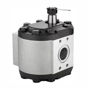
E6NN3K514AB Hydraulic Gear Pump for Ford Tractor 5110, 5610, 5900, 6410, 6610, 6810, 7010, 7610, 8010
The E6NN3K514AB hydraulic gear pump is a robust and reliable hydraulic pump, specially designed for Ford tractor models, including 5110, 5610, 5900, 6410, 6610, 6810, 7010, 7610 and 8010. This tractor hydraulic pump plays a crucial role in the tractor’s hydraulic system. It provides pressurized hydraulic oil to power various operations such as steering, lifting and other hydraulic functions. It is a gear pump that uses rotating gears to generate fluid flow, ensuring constant pressure and efficiency.
The E6NN3K514AB hydraulic gear pump is a robust and reliable hydraulic pump, specially designed for Ford tractor models, including 5110, 5610, 5900, 6410, 6610, 6810, 7010, 7610 and 8010. This tractor hydraulic pump plays a crucial role in the tractor's hydraulic system. It provides pressurized hydraulic oil to power various operations such as steering, lifting and other hydraulic functions. It is a gear pump that uses rotating gears to generate fluid flow, ensuring constant pressure and efficiency. This pump is manufactured in accordance with OEM specifications, ensuring its durability and compatibility with the aforementioned Ford tractor models.
E6NN3K514AB Hydraulic Gear Pump Specifications
| Applied to: | Ford Tractor 5110, 5610, 5900, 6410, 6610, 6810, 7010, 7610, 8010 |
| OEM Ref.No.: | E6NN3K514AB |
| Nominal Displacement: | 14.0ml/r |
| Maximum Pressure· | 225bar |
| Rotational Speed: | 3000r/min |
| Controlled Flow Rate: | 17.0L/min |
| Fuel Feed Hole: | 3/4-16UNF-2A |
| Fuel Discharge Hole: | 9/16-18UNF-2A |
| Direction of Rotation: | Left (Anti-clockwise) |
Tractor Hydraulic Gear Pump Design Features
- Robust Housing Construction
The tractor hydraulic gear pump features a durable cast iron or aluminum alloy housing. This design ensures resistance to high pressures and harsh operating conditions, providing longevity and reliability in demanding agricultural environments. - Precision-Ground Gears
The tractor hydraulic pump incorporates precision-ground gears, typically made of hardened steel, to ensure smooth operation and efficient fluid transfer. These gears minimize wear and maintain consistent hydraulic flow, critical for powering steering and other hydraulic systems in tractors. - High-Pressure Capability
Designed to handle pressures up to 225 bar, the hydraulic pump delivers sufficient force for tractor hydraulic systems. This capability supports consistent performance in tasks like steering and lifting, ensuring compatibility with models like the Ford 5610 and 7610. - Compact and Lightweight Design
The hydraulic gear pump’s compact design optimizes space within the tractor’s hydraulic system. Its lightweight construction, often using aluminum components, reduces overall vehicle weight, improving fuel efficiency while maintaining structural integrity for reliable operation in rugged conditions. - Efficient Flow Control Mechanism
Equipped with a flow control system, the tractor hydraulic pumps regulate hydraulic fluid delivery to maintain consistent performance. This feature prevents overloading and ensures smooth operation of hydraulic functions, enhancing tractor maneuverability and operational efficiency across various tasks.

Tractor Hydraulic Pump Working Principle
The working principle of the tractor hydraulic gear pump is to discharge hydraulic oil through interlocking gears. This pump adopts a positive displacement mechanism, delivering a fixed amount of hydraulic oil per revolution to ensure a constant flow rate. Due to its simple structure, high efficiency and reliability, it is one of the most commonly used types of hydraulic pumps in tractors.
This tractor hydraulic pump is composed of two meshing gears, which are installed in a sealed housing. One of the gears is called the drive gear and is connected to the power source of the tractor (usually the engine or the power output shaft), while the other gear is called the driven gear and rotates synchronously. When the gears rotate, two main chambers are formed: the oil inlet chamber for drawing in hydraulic oil and the oil outlet chamber for discharging pressurized hydraulic oil.
When the gear rotates, the teeth on the inlet side will separate, forming a low-pressure area. This pressure drop causes the hydraulic oil to be drawn into the oil inlet chamber from the oil tank. Then, the hydraulic oil flows around the outer edge of the gear in the sealed housing to ensure no leakage or backflow. As the gears continue to rotate, the teeth mesh again on the outlet side, squeezing out the retained hydraulic oil under high pressure.
Then, the pressurized hydraulic oil is guided through the tractor's hydraulic system to provide power for various functions, such as lifting equipment, steering or operation assistance equipment. The simple and efficient design of the hydraulic gear pump ensures stable performance, high reliability and easy maintenance, making it an ideal choice for heavy agricultural applications.

Additional information
| Edited by | Yjx |
|---|
Related products
-
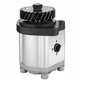
D8NN600FA Hydraulic Gear Pump for Ford Tractor 8200 8400 8600 9200 9600 9700
-

CBFZ-F32ALK1X Forklift Hydraulic Pumps
-
F0NN600AA Hydraulic Gear Pump for Ford Tractor 5640, 6640, 7740, 7840, 8240, 8340
-

CBDN-22/4JL Log Splitter Hydraulic Pump 2 Stage Log Splitter Pumps
-

D8NN600KB Hydraulic Gear Pump for Ford Tractor 5600, 6600, 6700, 7600, 7700