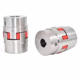
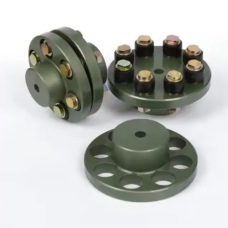
FCL Flexible Couplings
The FCL flexible coupling is renowned for its compact design, facilitating easy installation and convenient maintenance. Its small size and lightweight construction make it a preferred choice across various industries. When installed within specified tolerances, the FCL coupling operates optimally, ensuring smooth function and an extended working life. By accommodating relative displacement between shafts, it minimizes stress on connected equipment and enhances overall system performance. Trust in AGKNX the reliability and efficiency of the FCL flexible coupling to meet your industrial needs seamlessly. Experience the benefits of compactness, ease of installation, and durability with the FCL coupling.
The FCL flexible coupling is renowned for its compact design, facilitating easy installation and convenient maintenance. Its small size and lightweight construction make it a preferred choice across various industries. When installed within specified tolerances, the FCL coupling operates optimally, ensuring smooth function and an extended working life. By accommodating relative displacement between shafts, it minimizes stress on connected equipment and enhances overall system performance. Trust in AGKNX the reliability and efficiency of the FCL flexible coupling to meet your industrial needs seamlessly. Experience the benefits of compactness, ease of installation, and durability with the FCL coupling.
FCL Flexible Coupling Size Chart
 | 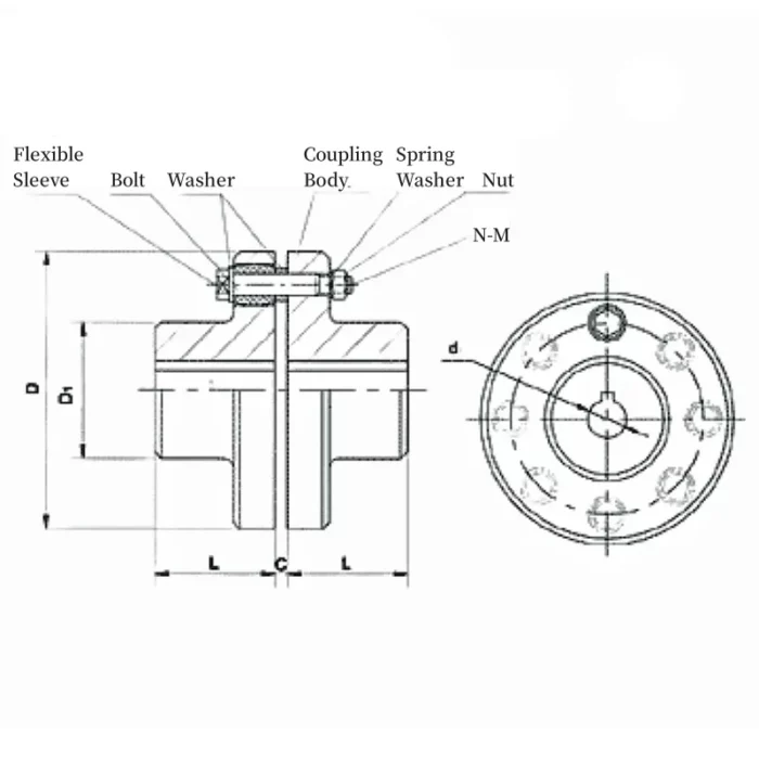 |
| Type | Max torque N.m | Max speed r/min | D | D₁ | d₁ | L | C | n-M | Weight kg |
|---|---|---|---|---|---|---|---|---|---|
| FCL90 | 4 | 4000 | 90 | 35.5 | 11 | 28 | 3 | 4-M8×50 | 1.7 |
| FCL100 | 10 | 4000 | 100 | 40 | 11 | 35.5 | 3 | 4-M10×56 | 2.3 |
| FCL112 | 16 | 4000 | 112 | 45 | 13 | 40 | 3 | 4-M10×56 | 2.8 |
| FCL125 | 25 | 4000 | 125 | 50 | 13 | 45 | 3 | 4-M12×64 | 4.0 |
| FCL140 | 50 | 4000 | 140 | 63 | 13 | 50 | 3 | 6-M12×64 | 5.4 |
| FCL160 | 110 | 4000 | 160 | 80 | 15 | 56 | 3 | 8-M12×64 | 8.0 |
| FCL180 | 157 | 3500 | 180 | 90 | 15 | 63 | 3 | 8-M12×64 | 10.5 |
| FCL200 | 245 | 3200 | 200 | 100 | 21 | 71 | 4 | 8-M20×85 | 16.2 |
| FCL224 | 392 | 2850 | 224 | 112 | 21 | 80 | 4 | 8-M20×85 | 21.3 |
| FCL220 | 618 | 2550 | 250 | 125 | 25 | 90 | 4 | 8-M24×110 | 31.6 |
| FCL280 | 980 | 2300 | 280 | 140 | 34 | 100 | 4 | 8-M24×116 | 44.0 |
| FCL315 | 1568 | 2050 | 315 | 160 | 41 | 112 | 4 | 10-M24×116 | 57.7 |
| FCL355 | 2450 | 1800 | 355 | 180 | 60 | 125 | 5 | 8-M30×50 | 89.5 |
| FCL400 | 3920 | 1600 | 400 | 200 | 60 | 125 | 5 | 10-M30×150 | 113 |
| FCL450 | 6174 | 1400 | 450 | 224 | 65 | 140 | 5 | 12-M30×150 | 145 |
| FCL560 | 9800 | 1150 | 560 | 250 | 85 | 160 | 5 | 14-M30×150 | 229 |
| FCL630 | 15680 | 1000 | 630 | 280 | 95 | 180 | 5 | 18-M30×150 | 296 |
Permittable relative displacement: Radial displacement: 0.2~0.6 mm, Angle displacement: 0°30'~1°30'
Advantages of FCL Flexible Couplings
FCL flexible couplings offer several advantages that make them a popular choice for various applications, particularly in medium and minor power transmission systems driven by motors. Here are the key benefits:
- Compact Design: FCL couplings are known for their space-saving structure, making them ideal for installations where size constraints are a concern.
- Easy Installation: Their straightforward design, typically consisting of a flange and coupling bolts, allows for quick and simple mounting, reducing setup time.
- Convenient Maintenance: Maintenance is hassle-free since components like bushings can often be replaced by simply removing the coupling bolts, minimizing downtime.
- Lightweight: The couplings are constructed to be light, which reduces the overall weight of the system and makes handling easier.
- Misalignment Compensation: FCL couplings can accommodate minor misalignments (radial and angular) between shafts within specified tolerances, ensuring smooth operation without excessive wear.
- Vibration and Noise Reduction: They absorb torsional vibrations, helping to dampen noise and protect connected equipment from vibrational stress.
- Durability: When operated within their specified limits, FCL couplings provide a long working life, making them reliable for sustained use in applications like speed reducers, hoists, compressors, conveyors, and ball mills.
- Cost-Effective: Their simple construction and efficient performance offer good value, balancing functionality with affordability.
FCL Flexible Coupling Applications
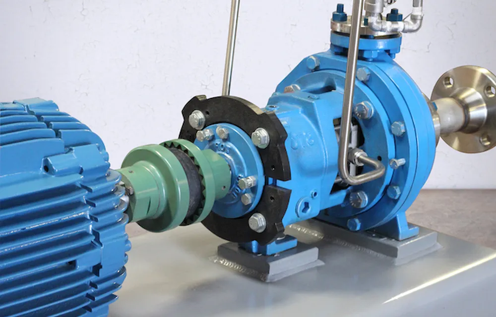
FCL flexible couplings are widely used in various industrial applications due to their ability to transmit torque between two shafts while accommodating misalignment, absorbing shock, and reducing vibration. These couplings are valued for their compact design, ease of installation, and low maintenance requirements. Below are some common applications of FCL flexible couplings:
- Pumps: FCL couplings connect pump motors to driven shafts, ensuring smooth power transmission while handling minor misalignments and vibrations caused by fluid dynamics.
- Compressors: In air or gas compressors, these couplings link the motor to the compressor unit, absorbing shocks and maintaining efficiency under varying loads.
- Conveyors: Used in material handling systems, FCL couplings join motors to conveyor drives, allowing for reliable operation even with slight shaft misalignments common in such setups.
- Blowers and Fans: They are employed to connect motors to blower or fan assemblies, reducing noise and vibration while ensuring consistent airflow.
- Cranes and Hoists: In lifting equipment, FCL couplings provide a flexible connection between the motor and gearbox, accommodating misalignment and load fluctuations.
- Cement Mixers: These couplings are used to link the motor to the mixing drum, enabling smooth operation despite the heavy, uneven loads typical in cement processing.
- Tractors: In agricultural machinery, FCL couplings connect engines to drivetrains or implements, offering durability and flexibility in rugged conditions.
- Rolling Mills: Found in metal processing, they transmit power between rollers and motors, handling misalignment and torsional stresses during operation.
- Spinning and Weaving Machinery: In textile manufacturing, FCL couplings ensure precise and smooth power delivery to spinning or weaving components, minimizing downtime.
- Speed Reducers: They are commonly paired with gearboxes to connect motors to output shafts, maintaining performance under varying speeds and loads.
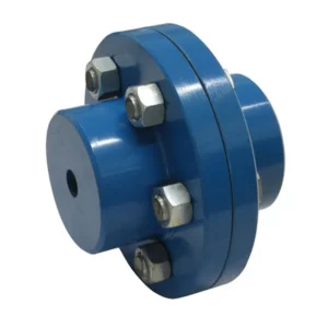
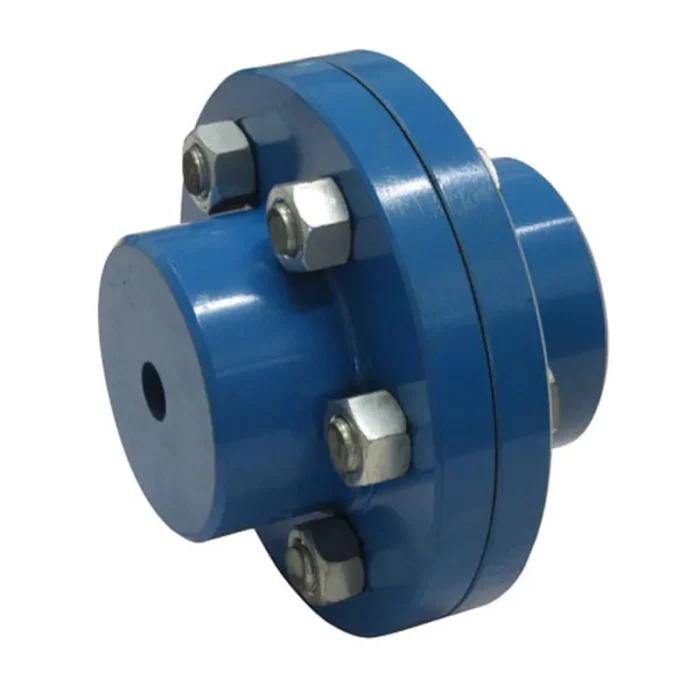
Rigid Coupling vs. Flexible Flange Coupling
A rigid coupling is a mechanical device that connects two shafts in a straight, fixed alignment, allowing no relative movement or flexibility. It ensures precise torque transmission and is ideal for applications requiring exact shaft alignment. In contrast, a flexible flange coupling connects shafts while accommodating minor misalignments, vibrations, or shocks. It features a flexible element, such as rubber or elastomeric material, between flanged hubs, providing adaptability and reducing stress on connected components. Rigid couplings are simpler and more cost-effective, while flexible flange couplings offer greater versatility and protection in dynamic systems.
| Aspect | Rigid Coupling | Flexible Flange Coupling |
|---|---|---|
| Definition | A coupling that rigidly connects two shafts without allowing relative motion. | A coupling that allows some degree of flexibility between connected shafts. |
| Flexibility | No flexibility; shafts must be perfectly aligned. | Offers flexibility to accommodate misalignment. |
| Misalignment Tolerance | Cannot tolerate any misalignment (angular, parallel, or axial). | Can handle angular, parallel, and axial misalignment to some extent. |
| Material | Typically made of steel or other rigid materials. | Often includes flexible elements like rubber or elastomers along with metal flanges. |
| Torque Transmission | Transmits torque directly with high efficiency. | Transmits torque effectively but with slight loss due to flexibility. |
| Vibration Damping | Does not dampen vibrations; transfers them fully. | Reduces vibrations and shocks due to flexible components. |
| Installation | Requires precise alignment during installation. | Easier to install due to tolerance for misalignment. |
| Maintenance | Low maintenance if alignment is perfect. | May require periodic inspection of flexible elements. |
| Cost | Generally less expensive due to simpler design. | More expensive due to complex design and materials. |
| Applications | Used in systems requiring precise shaft alignment (e.g., pumps, motors). | Used in systems with dynamic loads or misalignment (e.g., industrial machinery). |
| Durability | Highly durable under ideal conditions. | Durable but flexible components may wear over time. |
| Backlash | No backlash due to rigid connection. | Slight backlash possible due to flexible elements. |
| Size and Weight | Compact and lightweight design. | Larger and heavier due to additional components. |
| Operating Conditions | Best for stable, low-vibration environments. | Suitable for harsh, variable conditions. |
| Noise | May transmit more noise due to rigidity. | Quieter operation due to vibration damping. |
| Thermal Expansion | Less tolerant to shaft expansion or contraction. | Can accommodate thermal expansion better. |
| Assembly Complexity | Simple assembly with fewer parts. | More complex assembly with multiple components. |
| Load Capacity | High load capacity with no flexibility compromise. | Load capacity may be limited by flexible elements. |
 | |
| Rigid Coupling | Flexible Flange Coupling |
Additional information
| Edited by | Yjx |
|---|