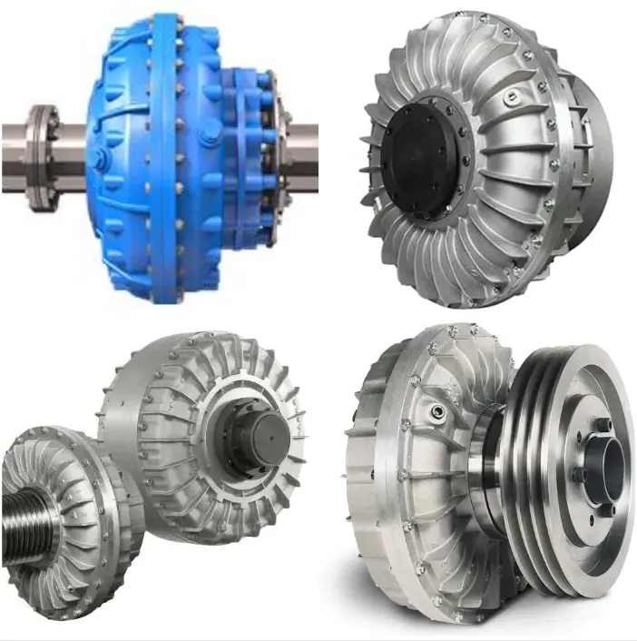
Fluid Couplings
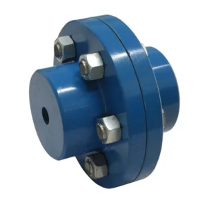
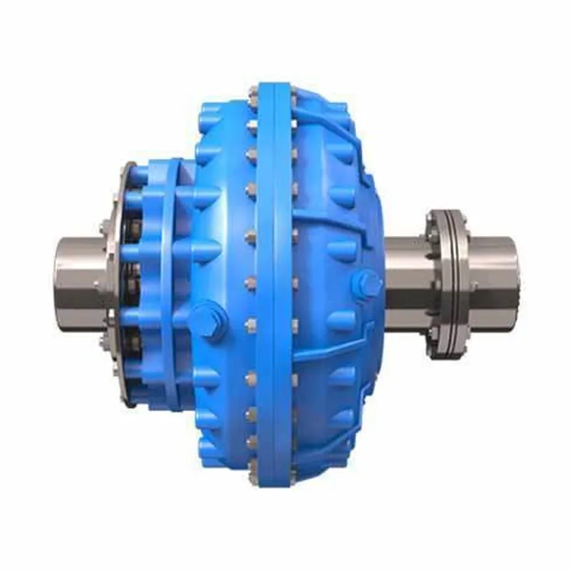
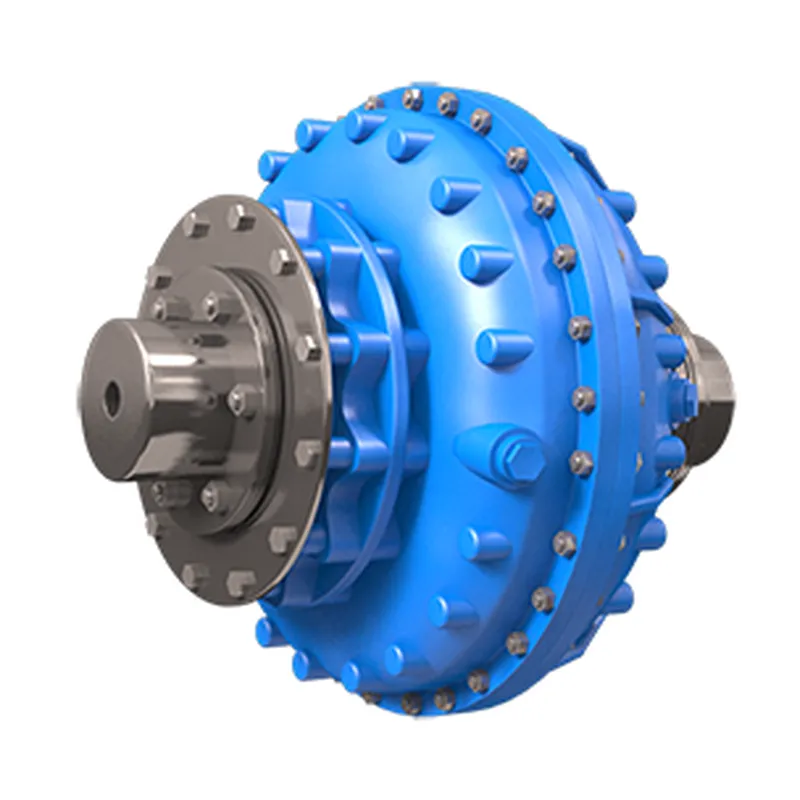
Fluid coupling is a hydrodynamic device used to transmit rotating mechanical power. It has widespread application in marine and industrial machine drives, where variable speed operation and controlled start-up without shock loading of the power transmission system is essential. A fluid coupling consists of three components, plus the hydraulic fluid. The housing, also known as the shell (which must have an oil-tight seal around the drive shafts), contains the fluid and turbines. Two turbines (fan like components), One connected to the input shaft known as the pump or impellor, and the other connected to the output shaft, known as the turbine, output turbine.
Fluid coupling is a hydrodynamic device used to transmit rotating mechanical power. It has widespread application in marine and industrial machine drives, where variable speed operation and controlled start-up without shock loading of the power transmission system is essential. A fluid coupling consists of three components, plus the hydraulic fluid. The housing, also known as the shell (which must have an oil-tight seal around the drive shafts), contains the fluid and turbines. Two turbines (fan like components), One connected to the input shaft known as the pump or impellor, and the other connected to the output shaft, known as the turbine, output turbine. The driving turbine is rotated by the prime mover. The impellor's motion imparts both outwards linear and rotational motion to the fluid. The hydraulic fluid is directed by the 'pump' whose shape forces the flow in the direction of the output turbine, thus causing it to rotate in the same direction as the pump.

Fluid Coupling Size Chart
Rating Table for HF/HFD/HF-DX Couplings
| COUPLING MODEL HF,HFD,HF-DX | Maximum Ratings in KW at Different Input Speeds RPM. | ||||||||
|---|---|---|---|---|---|---|---|---|---|
| 600 RPM | 730 RPM | 900 RPM | 970 RPM | 1200 RPM | 1470 RPM | 1800 RPM | *3000 RPM | *3600 RPM | |
| 1 | –– | 0.5 | 0.9 | 1.2 | 2.2 | 4 | 7.5 | 20 | 26 |
| 2 | –– | 0.9 | 1.7 | 2.2 | 4.1 | 7.5 | 13.7 | 30 | 36 |
| 3 | –– | 1.3 | 2.4 | 3 | 6 | 11 | 18 | 38 | 45 |
| 4 | 1 | 2 | 4 | 5 | 9 | 16.5 | 22 | 45 | –– |
| 5 | 2 | 4 | 7 | 9 | 16.3 | 30 | 42 | 70 | –– |
| 6 | 3 | 5 | 9 | 11 | 22 | 40 | 60 | 110 | –– |
| 7 | 4 | 8 | 15 | 18 | 34 | 62 | 85 | 140 | –– |
| 8 | 6 | 10 | 18 | 23 | 44 | 80 | 120 | –– | –– |
| 8 B | 9 | 16 | 29 | 36 | 68 | 125 | 180 | –– | –– |
| 9 | 12 | 22 | 41 | 52 | 98 | 172 | 246 | –– | –– |
| 9 B | 16 | 29 | 54 | 68 | 129 | 228 | 300 | –– | –– |
| 10 | 22 | 39 | 73 | 91 | 172 | 275 | 370 | –– | –– |
| 10 B | 32 | 57 | 107 | 134 | 253 | 373 | 500 | –– | –– |
| 11 | 47 | 85 | 158 | 198 | 374 | 525 | 775 | –– | –– |
| 12 | 82 | 148 | 278 | 348 | 600 | 750 | –– | –– | –– |
| 13 | 163 | 293 | 550 | 620 | 850 | 1100 | –– | –– | –– |
| 14 | 277 | 500 | 758 | 850 | 1250 | –– | –– | –– | –– |
| 15 | 472 | 850 | 1148 | 1250 | –– | –– | –– | –– | –– |
| 16 | 583 | 1050 | 1400 | 1500 | –– | –– | –– | –– | –– |
| 16 DC | 900 | 1500 | 1862 | 2000 | –– | –– | –– | –– | –– |
Coupling for 3000 RPM should be selected only after our approval is obtained.
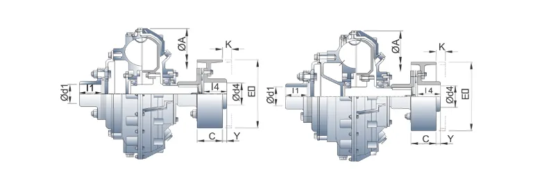
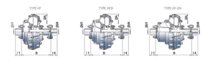
Specification and Dimension Table for HF, HFD, HF-DX Couplings
| Model HF,HFD,HF-DX | ø A | B | ø d1 ød4 max | ᶩ 1 & ᶩ 4 | * Dry Weight | Max. Oil Filling In Litres | Connected Flexible Coupling Model | ||||||
|---|---|---|---|---|---|---|---|---|---|---|---|---|---|
| HF | HFD | HF-DX | HF | HFD | HF-DX | HF | HFD | HF-DX | |||||
| 3 | 342 | 239 | 295 | 329 | 55 | 70 | 25 | 28 | 29 | 2.9 | 3.9 | 4.3 | FXC-I |
| 4 | 367 | 264 | 320 | 354 | 60 | 70 | 34 | 37 | 39 | 3.8 | 4.3 | 4.6 | FXC-II |
| 5 | 406 | 285 | 315 | 375 | 60 | 70 | 48 | 51 | 54 | 4.9 | 5.8 | 6.7 | FXC-II |
| 6 | 435 | 332 | 358 | 429 | 75 | 95 | 64 | 67 | 70 | 6.5 | 7.7 | 9.6 | FXC-IIIA |
| 7 | 471 | 345 | 390 | 460 | 75 | 95 | 81 | 84 | 86 | 8 | 9.4 | 11.3 | FXC-IIIA |
| 8 | 505 | 366 | 407 | 487 | 90 | 95 | 96 | 102 | 107 | 9.7 | 11.5 | 14.8 | FXC-III |
| 8 B | 553 | 405 | 445 | 535 | 90 | 110 | 116 | 122 | 127 | 14.5 | 16.1 | 19.1 | FXC-III |
| 9 | 584 | 395 | 445 | 526 | 90 | 110 | 124 | 130 | 135 | 16.1 | 19.3 | 20.8 | FXC-III |
| 9 B | 620 | 446 | 511 | 589 | 110 | 125 | 168 | 180 | 184 | 19.4 | 21.5 | 24.7 | FXC-IV A |
| 10 | 644 | 468 | 517 | 611 | 110 | 125 | 172 | 184 | 188 | 25.1 | 28.1 | 33.9 | FXC-IV A |
| 10 B | 714 | 491 | 537 | 632 | 110 | 125 | 217 | 233 | 237 | 31.8 | 36.5 | 45.4 | FXC-IV A |
| 11 | 751 | 511 | 566 | 661 | 115 | 125 | 281 | 292 | 300 | 37.1 | 42.9 | 49 | FXC-IV |
| 12 | 845 | 614 | 700 | 820 | 145 | 200 | 400 | 421 | 430 | 51.3 | 65.6 | 71.5 | FXC-V |
| 13 | 960 | 697 | 745 | 875 | 145 | 200 | 570 | 596 | 605 | 72.4 | 91.3 | 106.6 | FXC-V |
| 14 | 1104 | 770 | 813 | 943 | 220 | 200 | 640 | 688 | 703 | 114.7 | 131.9 | 153.9 | FXC-VI |
| 15 | 1230 | 777 | 886 | 1016 | 220 | 200 | 810 | 880 | 900 | 147.6 | 181.4 | 193.1 | FXC-VI |
| 16 | 1298 | 882 | 965 | 1095 | 220 | 200 | 1280 | 1320 | 1380 | 189.2 | 241.7 | 268.4 | FXC-VI |
- *Coupling for 3000RPM should be selected only after our approval is obtained.
- * With Connected Flexible Coupling.
Brake Drum Mounting (Outer Wheel Drive) Fluid Coupling Model HF, HFD, HF-DX
| Flexible Coupling Model | Metallic Disc Coupling | |||
|---|---|---|---|---|
| øE | C | Y | K* Min | |
| FXC-I | 160 | 75 | 21 | 26 |
| 200 | 75 | 21 | 26 | |
| FXC-II | 200 | 75 | 19 | 26 |
| 250 | 95 | 10 | 35 | |
| FXC-III A | 250 | 95 | 35 | 35 |
| 300 | 118 | 32 | 55 | |
| 315 | 118 | 32 | 55 | |
| FXC-III | 250 | 95 | 48 | 35 |
| 300 | 118 | 30 | 55 | |
| 315 | 118 | 30 | 55 | |
| 400 | 150 | 18 | 73 | |
| FXC-IV A | 300 | 118 | 52 | 55 |
| 315 | 118 | 52 | 55 | |
| 400 | 150 | 40 | 65 | |
| 500 | 190 | 5 | 70 | |
| FXC-IV | 400 | 150 | 40 | 65 |
| 500 | 190 | 5 | 70 | |
| 600 | 236 | (-)31 | 80 | |
| 630 | 236 | (-)31 | 80 | |
| FXC-V | 500 | 190 | 70 | 70 |
| 600 | 236 | 34 | 70 | |
| 630 | 236 | 34 | 70 | |
| 710 | 265 | 25 | 90 | |
- *For Radial Displacement of Fluid Coupling the Brake Drum shall need to be shifted by dimension 'K' as shown. The machine/G.B shaft length / space should be adequate for this shift of B.D.
Mass Moment of Inertia "J" With Oil in Kg M2
| Model | Outer Wheel | Inner Wheel |
|---|---|---|
| HF-3 | 0.25 | 0.05 |
| HF-4 | 0.39 | 0.07 |
| HF-5 | 0.66 | 0.23 |
| HF-6 | 0.69 | 0.29 |
| HF-7 | 1.32 | 0.35 |
| HF-8 | 1.72 | 0.49 |
| HF-8B | 2.4 | 0.64 |
| HF-9 | 2.82 | 0.76 |
| HF-9B | 4.65 | 1.91 |
| HF-10 | 5.01 | 2.11 |
| HF-10B | 10.15 | 3.34 |
| HF-11 | 11.66 | 3.93 |
| HF-12 | 18.3 | 7.31 |
| HF-13 | 35.74 | 14.25 |
| HF-14 | 61.46 | 24.1 |
| HF-15 | 93.13 | 37.24 |
| Model | Outer Wheel | Inner Wheel |
| HFD-3 | 0.26 | 0.05 |
| HFD-4 | 0.41 | 0.07 |
| HFD-5 | 0.71 | 0.24 |
| HFD-6 | 0.97 | 0.3 |
| HFD-7 | 1.46 | 0.4 |
| HFD-8 | 1.85 | 0.51 |
| HFD-8B | 2.61 | 0.72 |
| HFD-9 | 3.06 | 0.93 |
| HFD-9B | 5.09 | 1.96 |
| HFD-10 | 6.07 | 2.18 |
| HFD-10B | 11.3 | 3.44 |
| HFD-11 | 12.97 | 4.07 |
| HFD-12 | 20.33 | 7.61 |
| HFD-13 | 39.82 | 14.78 |
| HFD-14 | 68.04 | 24.98 |
| HFD-15 | 102.7 | 38.61 |
| HFD-16 | — | — |
| Model | Outer Wheel | Inner Wheel |
| HFDX-3 | 0.27 | 0.05 |
| HFDX-4 | 0.42 | 0.07 |
| HFDX-5 | 0.74 | 0.24 |
| HFDX-6 | 1.04 | 0.3 |
| HFDX-7 | 1.59 | 0.4 |
| HFDX-8 | 1.96 | 0.51 |
| HFDX-8B | 2.76 | 0.72 |
| HFDX-9 | 3.24 | 0.93 |
| HFDX-9B | 5.55 | 1.96 |
| HFDX-10 | 7.04 | 2.18 |
| HFDX-10B | 12.3 | 3.44 |
| HFDX-11 | 14.07 | 4.07 |
| HFDX-12 | 21.93 | 7.61 |
| HFDX-13 | 43.02 | 14.78 |
| HFDX-14 | 73.14 | 24.98 |
| HFDX-15 | — | — |
- * For fluid Coupling Model SM/SMD/SM-DX - 9B & 10.
Key Features of Fluid Couplings
Fluid couplings, also known as hydraulic couplings, are hydrodynamic devices used to transmit power between two shafts in a smooth and controlled manner. They are commonly employed in machinery, automotive systems, and industrial applications to provide variable speed control and protect equipment from shock loads. Here are the key features of fluid couplings:
- Smooth Power Transmission: Fluid couplings use a liquid medium (typically oil) to transmit torque, ensuring a gradual and smooth transfer of power between the input and output shafts. This eliminates mechanical jerks and reduces wear on components.
- Torque Multiplication: At startup, fluid couplings can multiply torque, allowing the driven machinery to accelerate gradually without overloading the driving motor.
- Slip Capability: They allow for controlled slip between the input and output shafts, meaning the speeds can differ slightly. This is useful for applications requiring flexibility, such as conveyor systems or vehicles.
- Overload Protection: By slipping under excessive load, fluid couplings act as a safety mechanism, protecting the drivetrain and connected machinery from damage due to sudden shocks or overloads.
- Vibration Damping: The fluid medium absorbs vibrations and torsional shocks, leading to quieter operation and increased lifespan of the system components.
- No Mechanical Contact: Since power is transmitted through fluid rather than direct mechanical connection, there’s minimal wear and tear, reducing maintenance needs.
- Variable Speed Control: Fluid couplings can be designed with adjustable features (e.g., variable fill designs) to control the amount of power transmitted, enabling speed regulation in certain applications.
- Heat Dissipation: The fluid absorbs and dissipates heat generated during operation, preventing overheating in high-power scenarios, though some designs may require external cooling for continuous heavy use.
- Applications: They are widely used in industries like mining, automotive (e.g., in automatic transmissions), power plants, and material handling systems (e.g., conveyors and crushers).
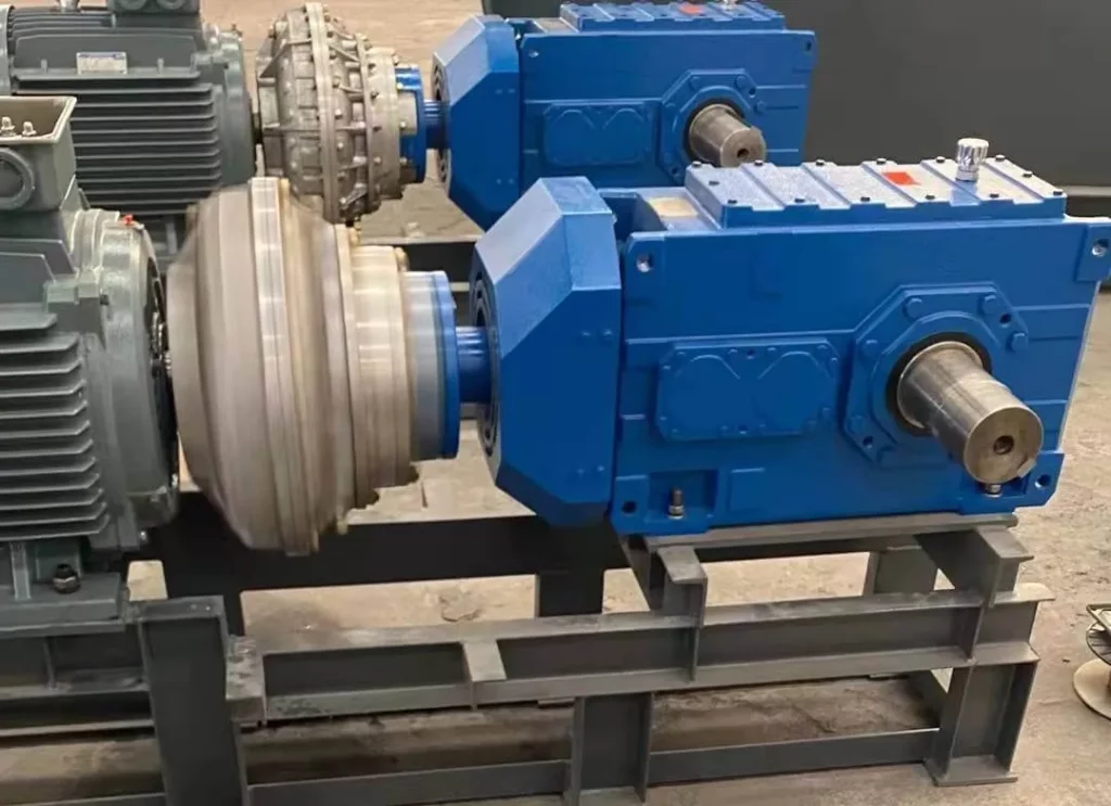
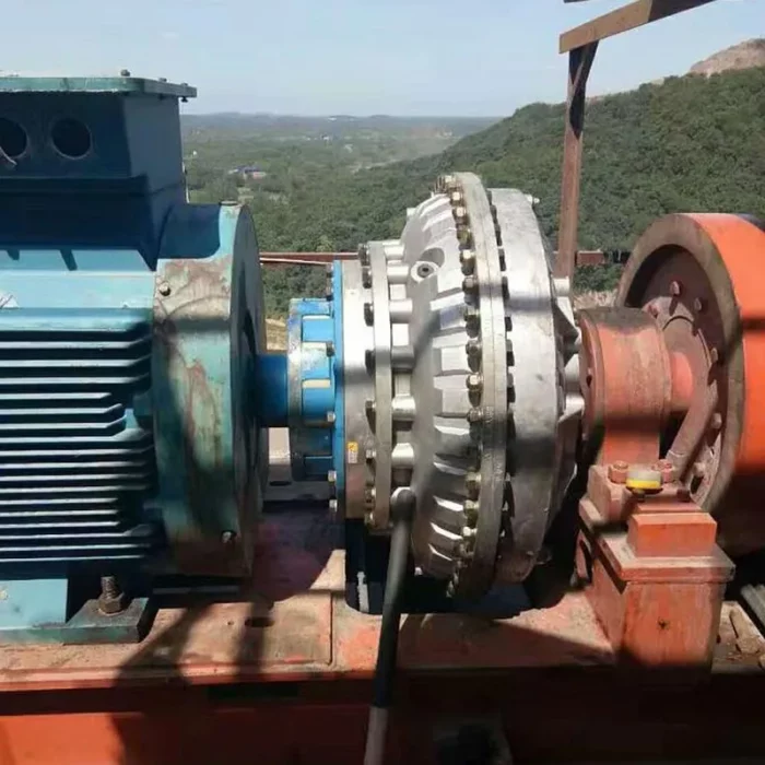
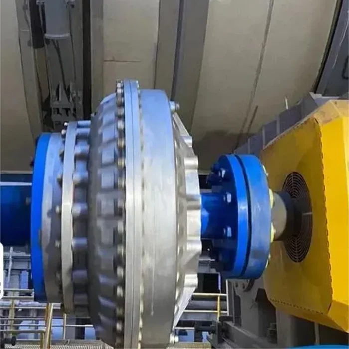
Fluid Coupling Applications
Fluid couplings are fascinating devices used in a variety of applications to transmit power smoothly and efficiently. They work by using a hydraulic fluid to transfer torque between two rotating shafts, typically an input (driving) and an output (driven) shaft, without a direct mechanical connection. This allows for controlled startups, shock absorption, and overload protection. Here are some key applications:
- Automotive Industry: Fluid couplings are integral in automatic transmissions, where they connect the engine to the transmission. They allow for smooth acceleration by gradually transferring torque, preventing sudden jolts, and protecting the drivetrain from shock loads during gear shifts.
- Industrial Machinery: In heavy machinery like conveyors, crushers, and mixers, fluid couplings provide a soft start, reducing mechanical stress. They help control torque, prevent overload, and extend equipment lifespan by cushioning the power transmission process.
- Mining Equipment: Fluid couplings are used in mining machinery such as belt conveyors and pumps. They enable controlled startups under heavy loads, minimizing wear on components and ensuring reliable operation in harsh, dusty environments.
- Marine Propulsion: In ships, fluid couplings connect engines to propellers, allowing smooth power transfer. They absorb vibrations and shocks from the engine, enhancing passenger comfort and reducing maintenance needs for marine drivelines.
- Power Generation: Fluid couplings are employed in power plants to drive equipment like fans, pumps, and turbines. They offer overload protection and smooth startups, improving efficiency and reducing downtime in critical energy systems.
- Construction Equipment: In machines like excavators and loaders, fluid couplings facilitate power transmission under variable loads. They ensure smooth operation, reduce strain on hydraulic systems, and improve fuel efficiency during demanding tasks.
 |  |
How Does a Hydraulic Fluid Coupling Work?
A hydraulic fluid coupling, also known as a fluid coupling or hydraulic clutch, is a device used to transmit rotational power between two shafts in a smooth and controlled manner. It’s commonly found in machinery like vehicles, industrial equipment, and conveyor systems, where it helps manage torque and protect components from sudden shocks or overloads. Here’s how it works:
At its core, a fluid coupling consists of two main parts: an impeller (connected to the input shaft, usually from a motor or engine) and a turbine (connected to the output shaft, driving the load). Both are housed in a sealed casing filled with hydraulic fluid, typically oil. These components look like fans or propellers facing each other, but they aren’t mechanically connected—power transfer happens entirely through the fluid.
When the input shaft spins the impeller, it accelerates the fluid inside the casing, creating a flow of kinetic energy. This moving fluid then strikes the turbine, causing it to rotate and drive the output shaft. The key is the fluid’s momentum: it acts as a "soft" link between the two parts, allowing power to transfer without a rigid connection. The speed difference (or slip) between the impeller and turbine depends on the load and fluid dynamics—under light loads, the turbine catches up quickly, while heavier loads increase slip, smoothing out torque spikes.
The design ensures a gradual buildup of power, which is why fluid couplings are great for starting heavy machinery without jerking or stalling the driving motor. Some couplings also include additional features like baffles or variable fill levels to tweak performance for specific applications.
Additional information
| Edited by | Yjx |
|---|