Gear Couplings
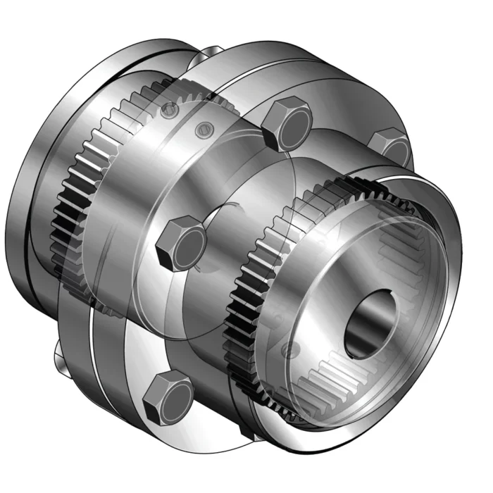
Gear couplings are torsionally rigid and are supplied in two designs – completely flexible and flexible/rigid. A completely flexible coupling comprises two hubs with an external gear and two outer sleeves with an internal gear. It’s a universal coupling for all sorts of applications and accommodates all possible misalignments (angular, offset, and combined) as well as large axial moments. Machines, bearings, seals, and shafts are therefore not subjected to the additional forces, sometimes of considerable magnitude, which arise from unavoidable misalignment usually associated with rigid shaft couplings.
Gear couplings are torsionally rigid and are supplied in two designs – completely flexible and flexible/rigid. A completely flexible coupling comprises two hubs with an external gear and two outer sleeves with an internal gear. It's a universal coupling for all sorts of applications and accommodates all possible misalignments (angular, offset, and combined) as well as large axial moments. Machines, bearings, seals, and shafts are therefore not subjected to the additional forces, sometimes of considerable magnitude, which arise from unavoidable misalignment usually associated with rigid shaft couplings.
Gear Coupling Size Chart
 |  |
 |  |
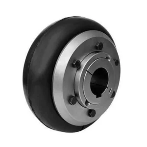
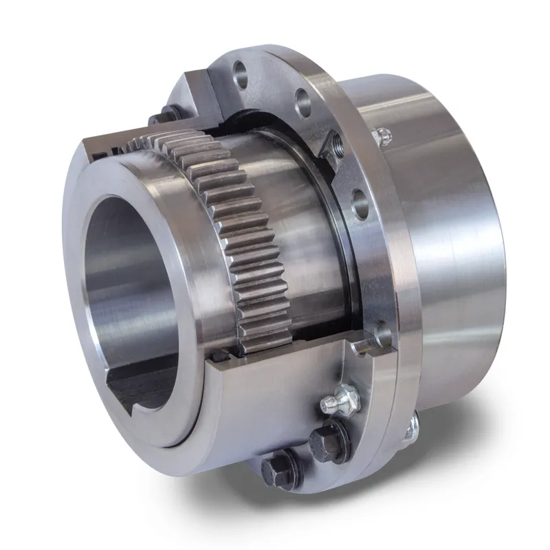
GD Type Gear Coupling
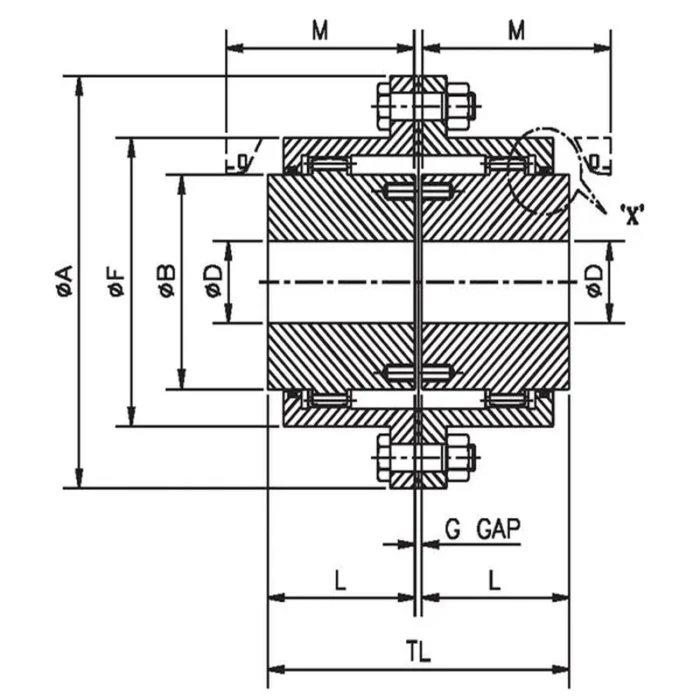
| Size | Coupling Rating | Maximum Speed rpm | Bore Dia OD mm | Dimensions mm | Solid Hub | |||||||||
| kW at 100 rpm | Rated Torque Nm | Min. Bore | Max. Bore | ØA | TL | L | ØB | ØF | M | Gap | Mass kg | M.I. (WR²) kg-m² | ||
| GD-10 | 14 | 1337 | 8000 | 14 | 52 | 116 | 89 | 43 | 69 | 84 | 51 | 3 | 4.4 | 0.0052 |
| GD-15 | 30 | 2865 | 6500 | 22 | 65 | 152 | 103 | 50 | 86 | 105 | 61 | 3 | 9 | 0.0192 |
| GD-20 | 53 | 5061 | 5600 | 27 | 80 | 178 | 127 | 62 | 105 | 127 | 76 | 3 | 15 | 0.041 |
| GD-25 | 105 | 10027 | 5000 | 32 | 98 | 213 | 159 | 77 | 131 | 155 | 92 | 5 | 27 | 0.105 |
| GD-30 | 168 | 16043 | 4400 | 42 | 115 | 240 | 187 | 91 | 152 | 181 | 106 | 5 | 40 | 0.195 |
| GD-35 | 231 | 22059 | 3900 | 47 | 135 | 279 | 220 | 107 | 178 | 211 | 130 | 6 | 65 | 0.454 |
| GD-40 | 336 | 32086 | 3600 | 47 | 160 | 318 | 248 | 121 | 210 | 250 | 145 | 6 | 96 | 0.86 |
| GD-45 | 472 | 45073 | 3200 | 52 | 180 | 346 | 278 | 135 | 235 | 274 | 165 | 8 | 131 | 1.39 |
| GD-50 | 650 | 62070 | 2900 | 72 | 195 | 389 | 314 | 153 | 254 | 306 | 183 | 8 | 186 | 2.53 |
| GD-55 | 880 | 84034 | 2650 | 72 | 215 | 425 | 344 | 168 | 279 | 334 | 203 | 8 | 247 | 3.83 |
| GD-60 | 1205 | 115069 | 2450 | 77 | 235 | 457 | 384 | 188 | 305 | 366 | 228 | 8 | 299 | 5.21 |
| GD-70 | 1823 | 174084 | 2150 | 92 | 280 | 527 | 451 | 221 | 356 | 425 | 266 | 9 | 473 | 11 |
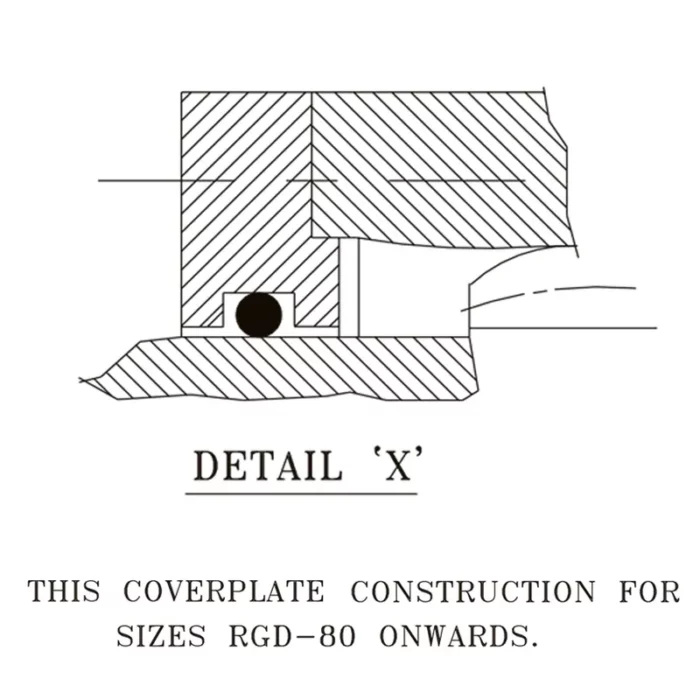
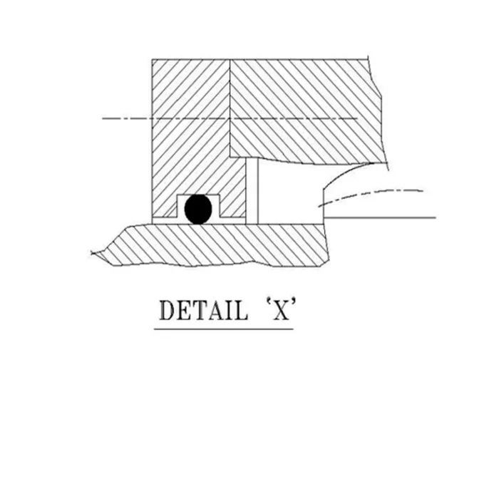
| GD-80 | 2639 | 252006 | 1750 | 95 | 285 | 590 | 508 | 249 | 385 | 485 | 300 | 10 | 682 | 20.72 |
| GD-90 | 3037 | 290012 | 1550 | 100 | 300 | 660 | 565 | 276 | 420 | 535 | 325 | 13 | 898 | 34.95 |
| GD-100 | 4100 | 391521 | 1450 | 120 | 330 | 711 | 623 | 305 | 470 | 595 | 355 | 13 | 1242 | 55.95 |
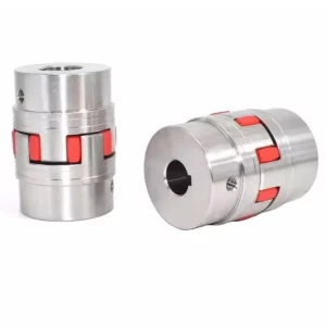
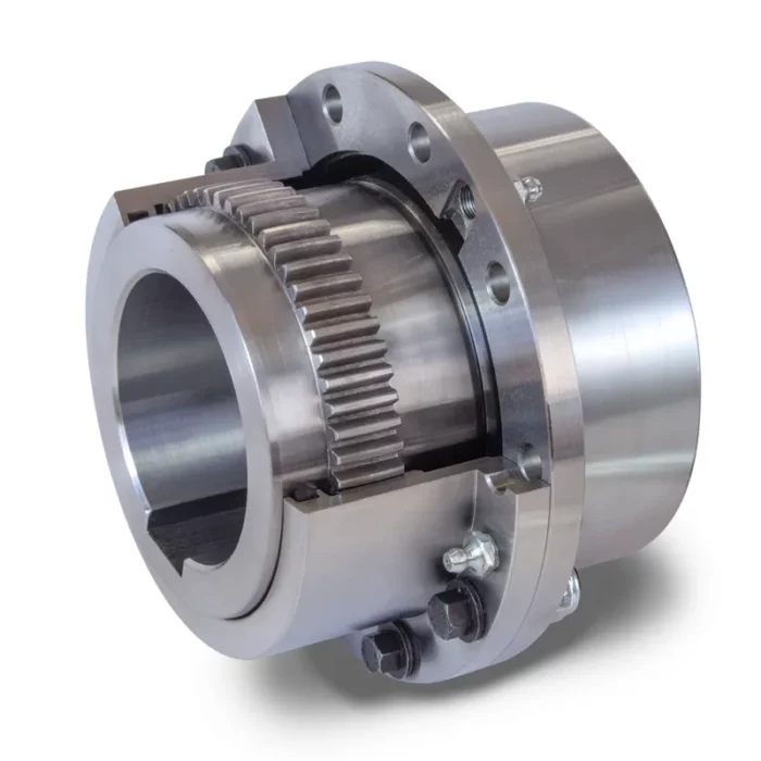
BGS Type Gear Coupling
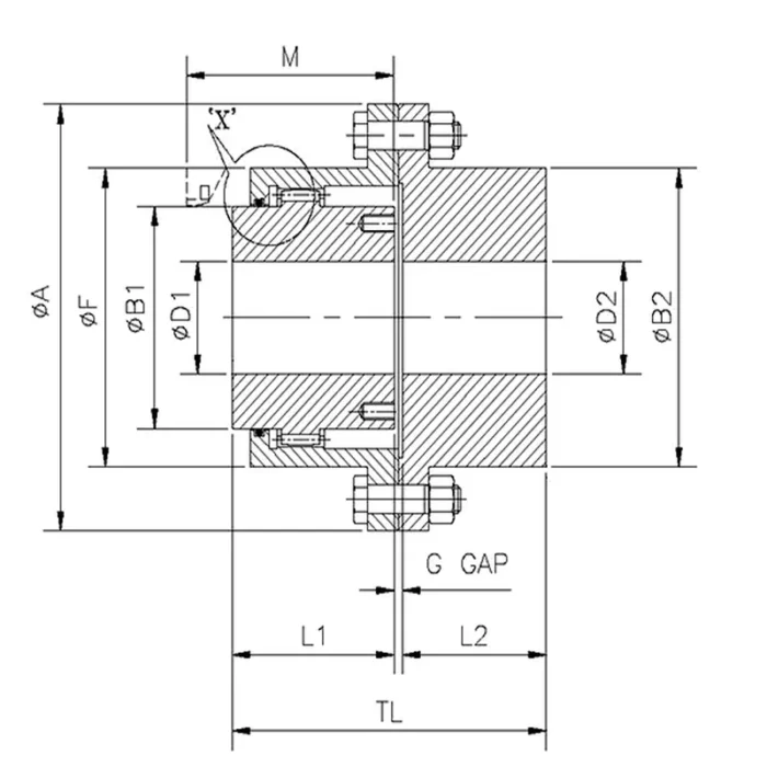 |  |
| Size | Coupling Rating | Max Speed rpm | Min. Bore Dia mm | Max. Bore Dia mm | Dimensions mm | Solid Hub | ||||||||||||
| kW at 100 rpm | Rated Torque kNm | Flex Hub | Rigid Hub | Flex Hub | Rigid Hub | ØA | TL1 | L | ØB1 | ØF | ØB2 | L2 | M | Gap | Mass kg | M.I. (WR²) Kg-m² | ||
| BGS-10 | 14 | 1337 | 8000 | 14 | 18 | 52 | 60 | 116 | 87 | 43 | 69 | 84 | 84 | 40 | 51 | 4 | 4.5 | 0.0055 |
| BGS-15 | 30 | 2865 | 6500 | 22 | 26 | 65 | 80 | 152 | 101 | 50 | 86 | 105 | 107 | 47 | 61 | 4 | 9.5 | 0.0204 |
| BGS-20 | 53 | 5061 | 5600 | 27 | 30 | 80 | 90 | 178 | 125 | 62 | 105 | 127 | 130 | 59 | 76 | 4 | 15.5 | 0.0436 |
| BGS-25 | 105 | 10027 | 5000 | 32 | 37 | 98 | 110 | 213 | 156 | 77 | 131 | 155 | 157 | 74 | 92 | 5 | 27.5 | 0.111 |
| BGS-30 | 168 | 16043 | 4400 | 42 | 44 | 115 | 130 | 240 | 184 | 91 | 152 | 181 | 182 | 88 | 106 | 5 | 41.5 | 0.210 |
| BGS-35 | 231 | 22059 | 3900 | 47 | 52 | 135 | 150 | 279 | 215 | 107 | 178 | 211 | 212 | 102 | 130 | 6 | 67 | 0.477 |
| BGS-40 | 336 | 32086 | 3600 | 47 | 52 | 160 | 180 | 318 | 245 | 121 | 210 | 246 | 250 | 116 | 145 | 8 | 100 | 0.92 |
| BGS-45 | 472 | 45073 | 3200 | 52 | 57 | 180 | 200 | 346 | 274 | 135 | 235 | 274 | 276 | 131 | 165 | 8 | 135 | 1.468 |
| BGS-50 | 650 | 62070 | 2900 | 72 | 77 | 195 | 220 | 389 | 310 | 153 | 254 | 306 | 309 | 148 | 183 | 9 | 195 | 2.73 |
| BGS-55 | 880 | 84034 | 2650 | 72 | 77 | 215 | 240 | 425 | 350 | 168 | 279 | 334 | 334 | 173 | 203 | 9 | 261 | 4.20 |
| BGS-60 | 1205 | 115069 | 2450 | 77 | 82 | 235 | 260 | 457 | 384 | 188 | 305 | 366 | 366 | 186 | 228 | 10 | 316 | 5.70 |
| BGS-70 | 1823 | 174084 | 2150 | 92 | 102 | 280 | 300 | 527 | 452 | 221 | 356 | 425 | 425 | 218 | 266 | 13 | 500 | 12.05 |
| BGS-80 | 2639 | 252006 | 1750 | 95 | 105 | 285 | 335 | 590 | 511 | 249 | 385 | 485 | 470 | 249 | 300 | 13 | 715 | 21.77 |
| BGS-90 | 3037 | 290012 | 1550 | 100 | - | 300 | 370 | 660 | 567 | 276 | 420 | 535 | 518 | 276 | 325 | 15 | 969 | 36.60 |
| BGS-100 | 4100 | 391521 | 1450 | 120 | - | 330 | 405 | 711 | 626 | 305 | 470 | 595 | 572 | 305 | 355 | 16 | 1259 | 56.27 |
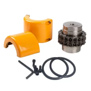
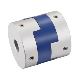
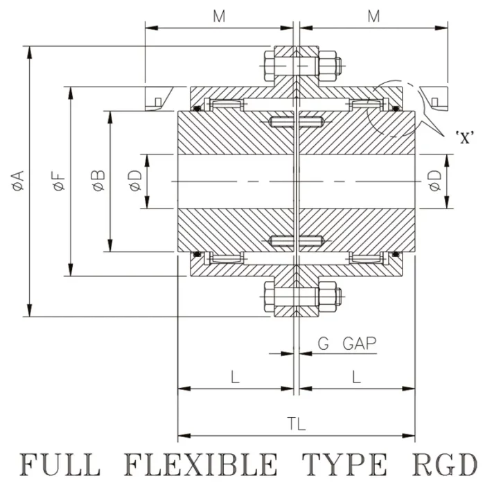
BVG Type Gear Coupling
Standard full flexible gear coupling type BVG accommodates angular & parallel misalignments or a combination of both as well as axial misalignment (end float). Ideal for all horizontal, close coupled applications including fans, overhead cranes, conveyors, steel & paper mill equipment. One or both of the hubs can be easily reversed for more than normal shaft separation applications.
 |  |
| Size | kW at 100 rpm | Rated Torque Nm | Max. rpm | Bore ØD | ØA | ØB | ØF | G | L | M | TL | # | ||
| wt. kg | M.I.(WR²) kg-m² | |||||||||||||
| PB | Max. | |||||||||||||
| BVG -100 | 6 | 559 | 7600 | 13 | 35 | 120 | 50 | 75 | 3 | 45 | 54 | 93 | 4.1 | 0.006 |
| BVG -101 | 12 | 1127 | 6730 | 14 | 50 | 170 | 65 | 110 | 5 | 55 | 67 | 115 | 10.6 | 0.029 |
| BVG -102 | 29 | 2804 | 6150 | 20 | 65 | 185 | 85 | 125 | 5 | 70 | 83 | 145 | 15.4 | 0.046 |
| BVG -103 | 53 | 5047 | 5200 | 30 | 80 | 220 | 105 | 150 | 5 | 85 | 103 | 175 | 26.0 | 0.110 |
| BVG -104 | 100 | 9557 | 4580 | 40 | 100 | 250 | 130 | 175 | 5 | 105 | 124 | 215 | 40.0 | 0.213 |
| BVG -105 | 152.94 | 14605 | 3950 | 46 | 115 | 290 | 155 | 200 | 10 | 110 | 136 | 230 | 60.0 | 0.445 |
| BVG -106 | 235 | 22444 | 3550 | 50 | 125 | 320 | 175 | 230 | 10 | 125 | 152 | 260 | 84.0 | 0.745 |
| BVG -107 | 412 | 39303 | 3270 | 60 | 145 | 350 | 205 | 260 | 10 | 140 | 174 | 290 | 113.4 | 1.21 |
| BVG -108 | 529 | 50472 | 3015 | 70 | 165 | 380 | 230 | 290 | 10 | 155 | 187 | 320 | 158.0 | 2.04 |
| BVG -109 | 658 | 62821 | 2650 | 80 | 190 | 430 | 250 | 330 | 10 | 165 | 196 | 340 | 210.0 | 3.46 |
| BVG -110 | 963 | 91923 | 2330 | 100 | 230 | 490 | 310 | 390 | 10 | 180 | 216 | 370 | 290.0 | 5.55 |
| BVG -111 | 1289 | 123065 | 2100 | 110 | 260 | 545 | 350 | 445 | 10 | 200 | 245 | 410 | 545.0 | 15.25 |
| BVG -112 | 1723 | 164516 | 1940 | 150 | 300 | 590 | 400 | 490 | 10 | 240 | 289 | 490 | 716.0 | 24.30 |
| BVG -113 | 2908 | 277694 | 1600 | 160 | 330 | 680 | 440 | 555 | 15 | 260 | 312 | 535 | 984.0 | 43.21 |
| BVG -114 | 4019 | 383786 | 1500 | 200 | 370 | 730 | 500 | 610 | 15 | 280 | 341 | 575 | 1219.0 | 64.84 |
| BVG -115 | 4812 | 459515 | 1400 | 230 | 410 | 780 | 540 | 660 | 15 | 320 | 385 | 655 | 1566.0 | 97.30 |
| BVG -116 | 7028 | 671165 | 1200 | 260 | 455 | 900 | 625 | 755 | 20 | 350 | 423 | 720 | 2246.0 | 183.66 |
| BVG -117 | 9997 | 954665 | 1100 | 300 | 520 | 1000 | 720 | 855 | 20 | 400 | 489 | 820 | 3260.0 | 338.05 |
| BVG -118 | 13236 | 1263938 | 1000 | 320 | 620 | 1100 | 810 | 950 | 20 | 450 | 533 | 920 | 4680.0 | 600.41 |
| BVG -119 | 17454 | 1666744 | 900 | 300 | 710 | 1250 | 910 | 1050 | 30 | 485 | 559 | 1000 | 6283.0 | 955.96 |
Advantages of the Gear Couplings
Gear couplings are mechanical devices used to connect two shafts, transmitting torque and accommodating misalignment between them. They are widely used in various industries due to their robust design and performance. Here are the key advantages of gear couplings:
- High Torque Transmission: Gear couplings are capable of transmitting high levels of torque, making them ideal for heavy-duty applications such as in steel mills, power plants, and industrial machinery.
- Accommodation of Misalignment: They can handle angular, parallel, and axial misalignment between connected shafts, reducing stress on equipment and improving operational reliability.
- Durability and Strength: Made from high-quality materials like steel, gear couplings are highly durable and resistant to wear, even under harsh operating conditions.
- Compact Design: Despite their strength, gear couplings have a relatively compact size, allowing them to fit into tight spaces in machinery layouts.
- Low Maintenance: Their simple design with fewer moving parts means gear couplings require minimal maintenance, reducing downtime and operational costs.
- Versatility: Gear couplings can be used in a wide range of applications, from high-speed machinery to low-speed, high-torque systems, making them adaptable to various industries.
- Shock Load Absorption: They can absorb and dampen shock loads and vibrations, protecting connected equipment from damage.
- High Efficiency: Gear couplings provide efficient power transmission with minimal energy loss, ensuring optimal performance of the system.
Typical Applications of Gear Couplings
Gear couplings are widely used in mechanical systems to transmit torque between two shafts that may not be perfectly aligned. Their design, which typically involves two hubs with external gear teeth and a sleeve with internal gear teeth, allows them to accommodate misalignment while delivering power efficiently. Here are some typical applications:
- Industrial Machinery: Gear couplings are common in heavy-duty equipment like steel rolling mills, paper mills, and cement mixers. They handle high torque loads and compensate for shaft misalignment caused by thermal expansion or operational stresses.
- Power Generation: In turbines, generators, and pumps, gear couplings connect driving and driven shafts. They’re valued for their ability to transmit large amounts of power reliably, even under varying alignment conditions.
- Automotive and Marine: They’re used in drivelines of heavy vehicles or ships, where misalignment between the engine and transmission can occur due to vibration or structural flexing.
- Mining Equipment: Crushers, conveyors, and hoists often rely on gear couplings. The rugged design withstands harsh environments and the misalignment from uneven loads or wear.
- Oil and Gas: Pumps, compressors, and drilling rigs use gear couplings to ensure consistent torque transfer, even when shafts shift slightly due to operational pressures or foundation settling.

Common Troubleshooting of Gear Couplings
Gear couplings are widely used in mechanical systems to transmit torque between two shafts while accommodating slight misalignments. However, like any mechanical component, they can encounter issues that require troubleshooting. Here are some common problems associated with gear couplings:
- Excessive Vibration: Gear couplings may experience excessive vibration due to misalignment between connected shafts, worn gear teeth, or improper installation. This can lead to uneven load distribution, causing noise and potential damage. Check alignment with precision tools and inspect teeth for wear.
- Overheating: Overheating occurs when lubrication is insufficient or degraded, or if the coupling is overloaded beyond its torque capacity. Friction increases, causing heat buildup. Regularly monitor lubricant condition, ensure proper grease levels, and verify the coupling’s load rating matches application demands.
- Noise During Operation: Unusual noises, such as grinding or clanking, often indicate misalignment, inadequate lubrication, or worn components. Metal-to-metal contact from insufficient grease can amplify sound. Inspect lubrication quality, re-align shafts, and replace damaged gears if necessary to restore smooth operation.
- Premature Wear of Gear Teeth: Gear teeth may wear out quickly due to improper lubrication, contamination in the lubricant, or excessive torque. This reduces efficiency and risks failure. Examine teeth for pitting or scoring, clean the coupling, and use high-quality, uncontaminated lubricant suited to operating conditions.
- Lubricant Leakage: Leaks can stem from damaged seals, over-pressurization during greasing, or worn housing components. Loss of lubrication accelerates wear and failure. Inspect seals for cracks, ensure proper greasing techniques, and replace faulty parts to maintain a sealed, lubricated environment.
- Shaft Misalignment: Misalignment—angular, parallel, or axial—strains the coupling, leading to vibration, wear, and potential breakdown. It’s often caused by installation errors or foundation settling. Use dial indicators or laser alignment tools to correct shaft positioning and secure mounting bases.
Additional information
| Edited by | Yjx |
|---|