HRC Couplings
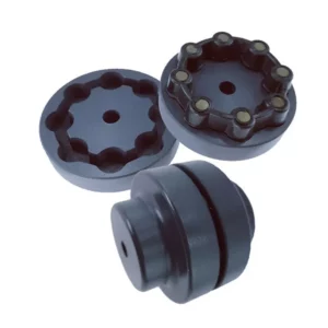
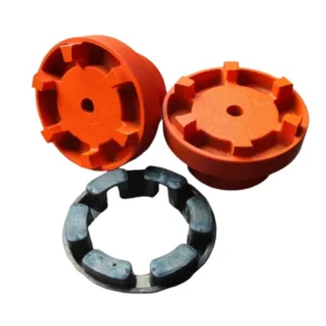
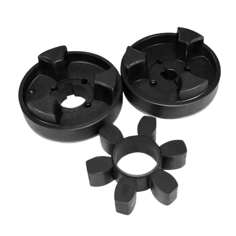
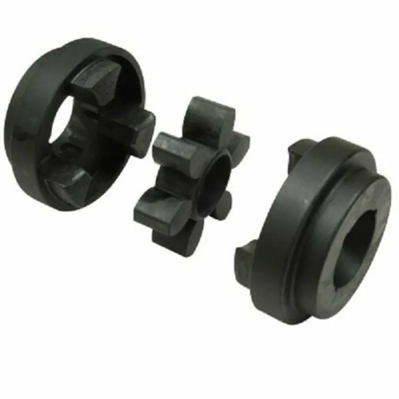
HRC Couplings are semi-elastic couplings tailored for general-purpose applications. Featuring versatile flange options, HRC Couplings are available in either F (with a taper bush that fits inside) or H (with a taper bush that fits outside), facilitating swift and effortless assembly via taper bush fixing onto the mating shaft. Alternatively, pilot bore flanges (PB) are offered, which can be conveniently bored to the desired shaft size. Inserts crafted from natural rubber are available for use within ambient temperatures ranging from -50°C to +50°C, ensuring optimal performance across diverse operating conditions.
HRC Couplings are semi-elastic couplings tailored for general-purpose applications. Featuring versatile flange options, HRC Couplings are available in either F (with a taper bush that fits inside) or H (with a taper bush that fits outside), facilitating swift and effortless assembly via taper bush fixing onto the mating shaft. Alternatively, pilot bore flanges (PB) are offered, which can be conveniently bored to the desired shaft size. Inserts crafted from natural rubber are available for use within ambient temperatures ranging from -50°C to +50°C, ensuring optimal performance across diverse operating conditions.
HRC Coupling Size Chart
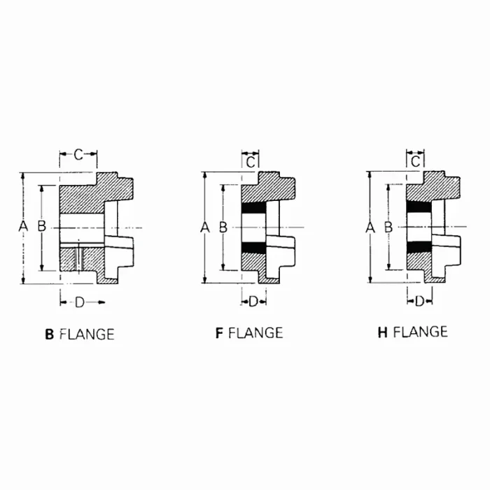 | 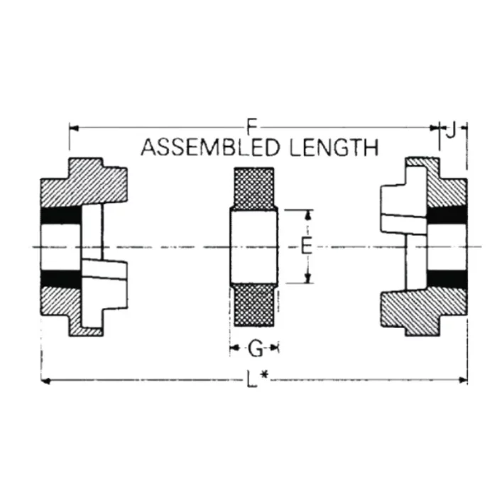 |
| Common Dimensions | Type F&H | Type B | ||||||||||||||
|---|---|---|---|---|---|---|---|---|---|---|---|---|---|---|---|---|
| Size | A mm | B mm | E mm | F1 mm | G mm | Bush size | Max.Bore | C mm | D mm | J mm | Bore Dia's | Screw over key | C mm | D mm | ||
| mm | inch | Max. mm | Pilot H9 | |||||||||||||
| HRC 70 | 69 | 60 | 31 | 25 | 18 | 1008 | 25 | 1 | 20 | 23.5 | 29 | 32 | 8 | M6 | 20 | 23.5 |
| HRC 90 | 85 | 70 | 32 | 30.5 | 22.5 | 1108 | 28 | 1 1/8 | 19.5 | 23.5 | 29 | 42 | 10 | M6 | 26 | 30.0 |
| HRC 110 | 112 | 100 | 45 | 45.0 | 29.0 | 1610 | 42 | 1 5/8 | 18.5 | 26.5 | 38 | 55 | 10 | M10 | 37 | 45.0 |
| HRC 130 | 130 | 105 | 50 | 53.0 | 36.0 | 1610 | 42 | 1 5/8 | 18.0 | 26.5 | 38 | 60 | 15 | M10 | 39 | 47.5 |
| HRC 150 | 150 | 115 | 62 | 60.0 | 40.0 | 2012 | 50 | 2 | 23.5 | 33.5 | 42 | 70 | 20 | M10 | 46 | 56.0 |
| HRC 180 | 180 | 125 | 77 | 73.0 | 49.0 | 2517 | 60 | 2 1/2 | 34.5 | 46.5 | 48 | 80 | 25 | M10 | 58 | 70.0 |
| HRC 230 | 225 | 155 | 99 | 85.5 | 59.5 | 3020 | 75 | 3 | 39.5 | 52.5 | 55 | 100 | 25 | M12 | 77 | 90.0 |
| HRC 280 | 275 | 206 | 119 | 105.5 | 74.5 | 3525 | 100 | 4 | 51.0 | 66.5 | 67 | 115 | 30 | M16 | 90 | 105.5 |
Key Features of HRC Couplings
“HRC coupling” typically refers to a type of flexible coupling used in mechanical engineering and industrial applications. The term “HRC” stands for “Highly Reliable Coupling” or “Highly Resilient Coupling.” These couplings are designed to transmit power and torque between two shafts while accommodating misalignment, vibration, and shock loads. They are commonly used in various machinery, including pumps, compressors, conveyors, and industrial equipment. Here are some key characteristics of HRC couplings include:
- Flexibility: HRC couplings are flexible and can tolerate angular, parallel, and axial misalignment between the connected shafts. This flexibility helps reduce the stress on the connected components and extends their lifespan.
- High Torsional Stiffness: Despite their flexibility, HRC couplings maintain high torsional stiffness, ensuring efficient power transmission and minimal torsional vibration.
- Resilience: HRC couplings are known for their ability to absorb shock loads and dampen vibrations, which helps protect the connected equipment from damage.
- Easy Installation: They are relatively easy to install and maintain, making them a popular choice in various industrial applications.
- Interchangeability: HRC couplings often follow standard sizes and dimensions, allowing for easy replacement and interchangeability.
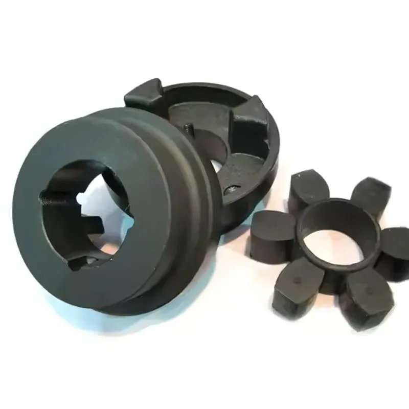
- Material Options: HRC couplings can be made from various materials, including cast iron, steel, or elastomers like rubber. The choice of material depends on the specific application’s requirements.
- Two-Piece Design: Many HRC couplings consist of two hubs and a flexible element (usually an elastomeric insert) that connects the hubs. This design simplifies installation and replacement.
HRC couplings are chosen for applications where flexibility, shock absorption, and alignment compensation are needed while maintaining reliable power transmission. They help protect connected equipment from damage due to misalignment or shock loads and contribute to the overall reliability and longevity of machinery and systems.
Common Applications of HRC Coupling
HRC (Highly Resilient Coupling) couplings are widely used in mechanical systems to connect two shafts for transmitting power while accommodating misalignment and dampening vibrations. Here are some common applications:
- Pumps and Compressors: HRC couplings are frequently used in industrial pumps and compressors, where they help transmit torque efficiently while reducing the impact of misalignment between the motor and the driven equipment.
- Conveyor Systems: In manufacturing and material handling, HRC couplings connect motors to conveyor belts, ensuring smooth operation and absorbing shocks caused by load variations.
- Fans and Blowers: These couplings are employed in HVAC systems and industrial fans to link motors with fan shafts, minimizing vibration and noise while maintaining reliable power transmission.
- Generators: HRC couplings are used in power generation setups to connect engines or turbines to generators, providing flexibility and resilience under varying loads.
- Mixers and Agitators: In chemical, food processing, and pharmaceutical industries, HRC couplings are applied in mixers and agitators to handle misalignment and protect equipment from torsional stress.
- Machine Tools: They are used in lathes, milling machines, and other precision equipment to ensure smooth power transfer and reduce wear on components.
Their popularity stems from their ability to handle moderate misalignment, absorb shocks, and provide a cost-effective solution for a wide range of industrial applications. The rubber element in HRC couplings also helps in reducing maintenance needs by cushioning impacts and extending the lifespan of connected machinery.

How to Choose the Right HRC Coupling for Your Needs
Choosing the right HRC coupling for your needs involves evaluating several key factors to ensure optimal performance, durability, and compatibility with your application. HRC couplings are popular for their flexibility, ability to absorb shock, and accommodation of misalignment between shafts. Here’s a step-by-step guide to help you make the right choice:
1. Understand Your Application Requirements
- Torque Transmission: Determine the torque (in Nm or lb-ft) your system needs to transmit. Check the motor or driver’s rated torque and account for any peak loads or shock loads during operation.
- Speed (RPM): Identify the operating speed of your system. HRC couplings have maximum RPM limits, so ensure the coupling can handle your application’s speed.
- Power: Calculate the power (in kW or HP) transmitted through the coupling using the formula:
Power (kW) = (Torque × RPM) / 9550. Ensure the coupling’s power rating exceeds this value.
2. Assess Misalignment Tolerance
- HRC couplings can accommodate angular, parallel, and axial misalignment to a degree. Measure the expected misalignment in your setup:
- Angular Misalignment: Angle between the shafts (typically up to 1° for HRC couplings).
- Parallel Misalignment: Offset between shaft centers (usually a few millimeters).
- Axial Movement: End float or thermal expansion along the shaft.
- Choose a coupling size and design that can handle these tolerances without excessive wear.
3. Select the Coupling Size
- HRC couplings come in various sizes (e.g., HRC 70, 90, 110, 130, etc.), each with a specific torque and bore capacity. Refer to the product catalog for a size chart:
- Match the torque requirement to the coupling’s rated torque (include a safety factor, typically 1.5–2x the operating torque).
- Ensure the shaft diameters of your driver and driven equipment fit within the coupling’s bore range (minimum and maximum diameters).
4. Choose the Material and Taper Bush
- Hub Material: Most HRC couplings use cast iron hubs for durability. For corrosive environments, consider stainless steel or coated options if available.
- Element Material: The flexible element (often rubber or polyurethane) absorbs shock and vibration. Select a hardness (e.g., Shore A 80–95) based on your need for flexibility vs. torque capacity:
- Softer elements = better damping, lower torque.
- Harder elements = higher torque, less flexibility.
- Taper Bush: HRC couplings typically use taper lock bushes for easy installation and removal. Match the bush size to your shaft diameter.
5. Consider Environmental Conditions
- Temperature: Check the operating temperature range of the coupling’s flexible element (e.g., -40°C to 100°C for standard rubber). High-temperature applications may require special materials.
- Exposure: If the coupling will be exposed to chemicals, oil, or moisture, choose a resistant element material (e.g., nitrile rubber or polyurethane).
- Space Constraints: Ensure the coupling’s outer diameter and length fit within your system’s physical layout.
Additional information
| Edited by | Yjx |
|---|