Oldham Couplings
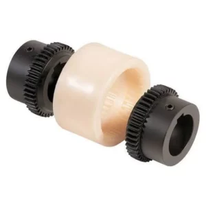
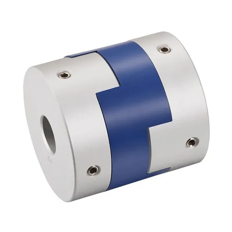
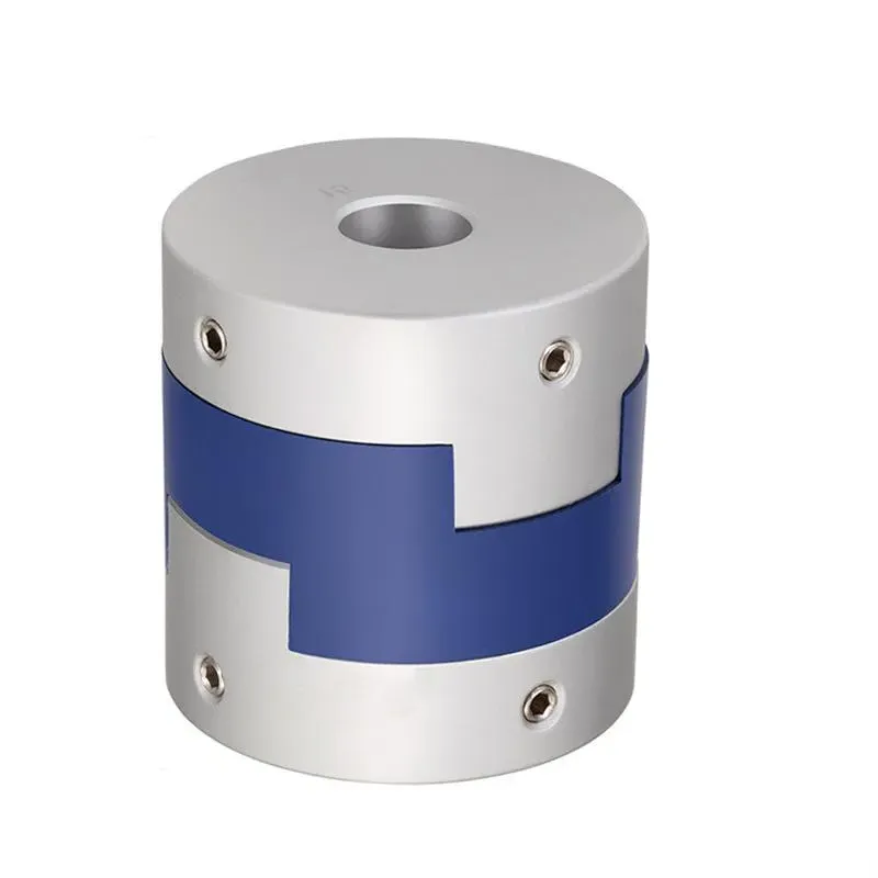
An Oldham coupling is a type of flexible shaft coupling used to connect two rotating shafts that are slightly misaligned, allowing them to transmit torque effectively while accommodating parallel misalignment. It consists of three main components: two hubs and a central disc. Each hub is attached to one of the shafts, and the central disc, typically made of a durable material like metal or plastic, connects the hubs via tongues or slots. These tongues fit into corresponding grooves on the hubs, positioned at 90 degrees to each other, enabling the coupling to slide and compensate for misalignment.
An Oldham coupling is a type of flexible shaft coupling used to connect two rotating shafts that are slightly misaligned, allowing them to transmit torque effectively while accommodating parallel misalignment. It consists of three main components: two hubs and a central disc. Each hub is attached to one of the shafts, and the central disc, typically made of a durable material like metal or plastic, connects the hubs via tongues or slots. These tongues fit into corresponding grooves on the hubs, positioned at 90 degrees to each other, enabling the coupling to slide and compensate for misalignment. The design ensures smooth power transmission, reduces wear on machinery, and tolerates small angular and axial misalignments, though it’s primarily suited for parallel offset.
Oldham Coupling Size Chart
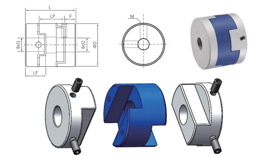
Dimension table | mm | |||||||
Model | Common DL / D2 inner diameter size | ΦD | L | LF | LP | F | M | Tightening torque (n.m) |
GL-16X18 | 4-5-6-6.35-7-8 | 16 | 18 | 7.1 | 12 | 3.0 | M3 | 1.2 |
GL-20X23 | 5-6-6.35-7-8 | 20 | 23 | 9 | 12.7 | 4.5 | M4 | 1.7 |
GL-20X25 | 5-6-6.35-8-9-9.525-10 | 20 | 25 | 10.1 | 12.7 | 3.0 | M4 | 2.5 |
GL-25X28 | 5-6-8-9-9.525-10-11-12-14 | 25 | 28 | 21 | 17.7 | 2.8 | M4 | 2.5 |
GL-32X33 | 5-6-8-9-9.525-10-11-12-12.7-14-15-16 | 32 | 33 | 14 | 20 | 3.4 | M4 | 2.5 |
GL-40X32 | 8-9-9.525-10-11-12-12.7-14-15-16-17-18-19-20 | 40 | 32 | 14 | 20.3 | 3.2 | M4 | 2.5 |
GL-44X46 | 8-9-9.525-10-11-1212.7-14-15-16-17-18-19-20-22 | 44 | 46 | 20.7 | 18.4 | 3.5 | M5 | 5 |
GL-50X38 | 10-12-12.7-14-15-16-17-18-19-20-22-24-25 | 50 | 38 | 16.5 | 22.35 | 3.8 | M5 | 5 |
GL-55X57 | 10-12-12.7-14-15-16-17-18-19-20-22-24-25-28-30-32 | 55 | 57 | 26.2 | 25.8 | 7.8 | M5 | 5 |
GL-63X47 | 14-15-16-17-18-19-20-22-24-25-28-30-32 | 63 | 47 | 21 | 25.8 | 6.0 | M6 | 8 |
GL-70X77 | 16-17-18-19-20-22-24-25-28-30-32-25-38-40 | 70 | 77 | 37 | 25 | 13.5 | M8 | 20 |
Technical Parameter
Technical parameter | mm | |||||||
Model | Rated torque (N.m) | Allowable eccentricity (mm) | Allowable deflection angle (∠。) | Allowable axial deviation (mm) | Allowable speed (RPM) | Static torsional stiffness (N.m/rad) | Moment of inertia (N.m) | Coupling weight (g) |
GL-16X18 | 0.7 | 0.8 | 3 | ±0.2 | 9000 | 30 | 3.0X10⁻⁷ | 6 |
GL-20X23 | 1.2 | 1.5 | 3 | ±0.2 | 3100 | 60 | 1.0X10⁻⁶ | 14 |
GL-20X25 | 1.25 | 1.2 | 3 | ±0.2 | 7000 | 58 | 3.0X10⁻⁷ | 18 |
GL-25X28 | 2 | 1.6 | 3 | ±0.2 | 6000 | 130 | 2.8X10⁻⁶ | 25 |
GL-32X33 | 4.5 | 2 | 3 | ±0.2 | 4800 | 270 | 8.9X10⁻⁵ | 44 |
GL-40X32 | 9 | 2.4 | 3 | ±0.2 | 3600 | 520 | 2.1X10⁻⁵ | 81 |
GL-44X46 | 12 | 2.8 | 3 | ±0.2 | 3500 | 560 | 3.8X10⁻⁵ | 136 |
GL-50X38 | 19 | 2.6 | 3 | ±0.2 | 3000 | 800 | 6.0X10⁻⁵ | 142 |
GL-55X57 | 22 | 3.3 | 3 | ±0.2 | 2800 | 795 | 9.9X10⁻⁵ | 255 |
GL-63X47 | 33 | 3 | 3 | ±0.2 | 2500 | 1200 | 2.1X10⁻⁴ | 320 |
GL-70X77 | 56 | 3.8 | 3 | ±0.2 | 2500 | 1260 | 3.9X10⁻⁴ | 445 |
Comparison table of keyway processing dimensions
Shaft diameter dimension | Standard machining dimension of the keyway | Keyway size | |||
dl/d2 | b | t | (bxh) | ||
Slot width | tolerance | slot depth | tolerance | ||
Φ6-Φ7.9 | 2 | ±0.0125 | 1.0 | ±0.10 | 2X2 |
Φ8-Φ10 | 3 | ±0.0150 | 1.4 | 3X3 | |
Φ10.1-Φ12 | 4 | 1.8 | 4X4 | ||
Φ12.1-Φ17 | 5 | 2.3 | 5X5 | ||
Φ17.1-Φ22 | 6 | ±0.0180 | 2.8 | 6X6 | |
Φ22.1-Φ30 | 8 | 3.3 | ±0.20 | 8X7 | |
Φ30.1-Φ38 | 10 | ±0.0215 | 3.3 | 10X8 | |
Φ38.1-Φ44 | 12 | 3.8 | 12X8 | ||
Φ44.1-Φ50 | 14 | 4.3 | 14X9 | ||
Φ50.1-Φ58 | 16 | 4.4 | 16X10 | ||
Φ58.1-Φ65 | 18 | 4.4 | 18X11 | ||
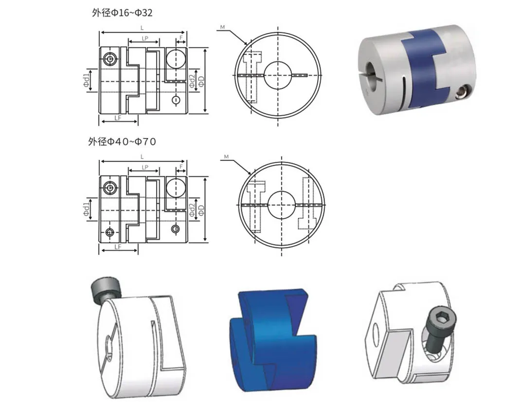
Outline Dimension Table
Outline dimension table | mm | |||||||
Model | Common DL / D2 inner diameter size | ΦD | L | LF | LP | F | M | Tightening torque (n.m) |
GLC-16X29 | 4-5-6-6.35 | 16 | 29 | 12.5 | 12 | 3 | M2.5 | 0.8 |
GLC-20X33 | 5-6-6.35-7-8 | 20 | 33 | 14.1 | 12.7 | 3.8 | M2.5 | 0.8 |
GLC-25X39 | 5-6-6.35-8-9-9.525-10-11-12 | 25 | 39 | 16.9 | 17.7 | 3.9 | M3 | 1.2 |
GLC-32X45 | 5-6-8-9-9.525-10-11-12-12.7-14-15-16 | 32 | 45 | 20 | 20 | 4.5 | M4 | 2.5 |
GLC-40X50 | 8-9-9.525-10-11-12-14-15-16-17-18-19 | 40 | 50 | 23 | 20.3 | 5.5 | M5 | 5 |
GLC-44X46 | 8-9-9.525-10-11-12-14-15-16-17-18-19-20-22 | 44 | 46 | 20.7 | 18.4 | 7 | M5 | 5 |
GLC-50X53 | 10-11-12.7-14-15-16-17-18-19-20-22-24 | 50 | 53 | 24.2 | 22.35 | 7.5 | M6 | 8 |
GLC-50X58 | 10-11-12.7-14-15-16-17-18-19-20-22-24 | 50 | 58 | 26.5 | 22.35 | 6.3 | M6 | 8 |
GLC-55X57 | 10-11-12.7-14-15-16-17-18-19-20-22-24-25-28 | 55 | 57 | 26.2 | 25.8 | 6.3 | M6 | 8 |
GLC-63X71 | 14-15-16-17-18-19-20-22-24-25-28-30-32 | 63 | 71 | 32.8 | 26.2 | 7.8 | M8 | 20 |
GLC-70X77 | 14-15-16-17-18-19-20-22-24-25-28-30-32-35-38 | 70 | 71 | 37 | 25 | 7.7 | M8 | 20 |
Technical Parameter
Technical parameter | m m | ||||||||
| Model | Rated torque (N.m) | Allowable eccentricity (mm) | Allowable deflection angle (∠。) | Allowable axial deviation (mm) | Allowable speed (RPM) | Static torsional stiffness (N.m/rad) | Moment of inertia (N.m) | Coupling weight (g) | |
| GLC-16X29 | 0.7 | 0.8 | 3 | ±0.2 | 9000 | 30 | 3.5X10⁻⁷ | 12 | |
| GLC-20X33 | 1..2 | 1.2 | 3 | ±0.2 | 7000 | 58 | 1.5X10⁻⁶ | 19 | |
| GLC-25X39 | 2 | 1.6 | 3 | ±0.2 | 6000 | 130 | 3.2X10⁻⁶ | 35 | |
| GLC-32X45 | 4.5 | 2 | 3 | ±0.2 | 4800 | 270 | 1.5X10⁻⁵ | 67 | |
| GLC40X50 | 9 | 2.4 | 3 | ±0.2 | 3600 | 520 | 4.2X10⁻⁵ | 114 | |
| GLC-44X46 | 12 | 2.5 | 3 | ±0.2 | 3500 | 800 | 4.5X10⁻⁵ | 140 | |
| GLC-50X53 | 19 | 2.6 | 3 | ±0.2 | 3000 | 800 | 1.0X10⁻⁴ | 190 | |
| GLC-50X58 | 19 | 3 | 3 | ±0.2 | 3000 | 800 | 1.1X10⁻⁴ | 215 | |
| GLC-55X57 | 25 | 3.2 | 3 | ±0.2 | 3000 | 900 | 1.3X10⁻⁵ | 260 | |
| GLC-63X71 | 33 | 3 | 3 | ±0.2 | 2550 | 1200 | 3.5X10⁻⁴ | 455 | |
| GLC -70X77 | 56 | 3.5 | 3 | ±0.2 | 2500 | 1260 | 4.1X10⁻⁴ | 520 | |
Advantages of the Oldham Couplings
Oldham couplings are a type of flexible coupling used in mechanical systems to transmit torque between two shafts that may not be perfectly aligned. Here are the key advantages of Oldham couplings:
- Misalignment Compensation: Oldham couplings can accommodate both angular and parallel misalignment between shafts. This makes them ideal for applications where precise alignment is difficult to achieve or maintain.
- Torque Transmission: They efficiently transmit torque while maintaining constant velocity, ensuring smooth operation without introducing significant rotational irregularities.
- Vibration Damping: The design, which typically includes a central disc (often made of plastic or a softer material) sliding between two hubs, helps absorb and dampen vibrations and shocks, reducing wear on connected components.
- Ease of Assembly and Maintenance: Oldham couplings are relatively simple to install and disassemble. The sliding disc can be replaced easily if worn, making maintenance straightforward and cost-effective.
- Backlash-Free Operation: When properly designed and maintained, Oldham couplings provide near-zero backlash, which is critical in precision applications like robotics or CNC machinery.
- Compact Design: They have a compact and lightweight structure, making them suitable for systems where space and weight are constraints.
Applications of the Oldham Couplings
Oldham couplings are mechanical devices used to connect two rotating shafts, allowing them to transmit torque while accommodating misalignment. They consist of three main components: two hubs (one attached to each shaft) and a central disc that slides between them. Here are some key applications of Oldham couplings:
- Misalignment Compensation in Machinery: Oldham couplings are widely used in systems where shafts are slightly misaligned—either parallel or angular. They’re ideal for applications like pumps, motors, and gearboxes, where perfect alignment isn’t always practical.
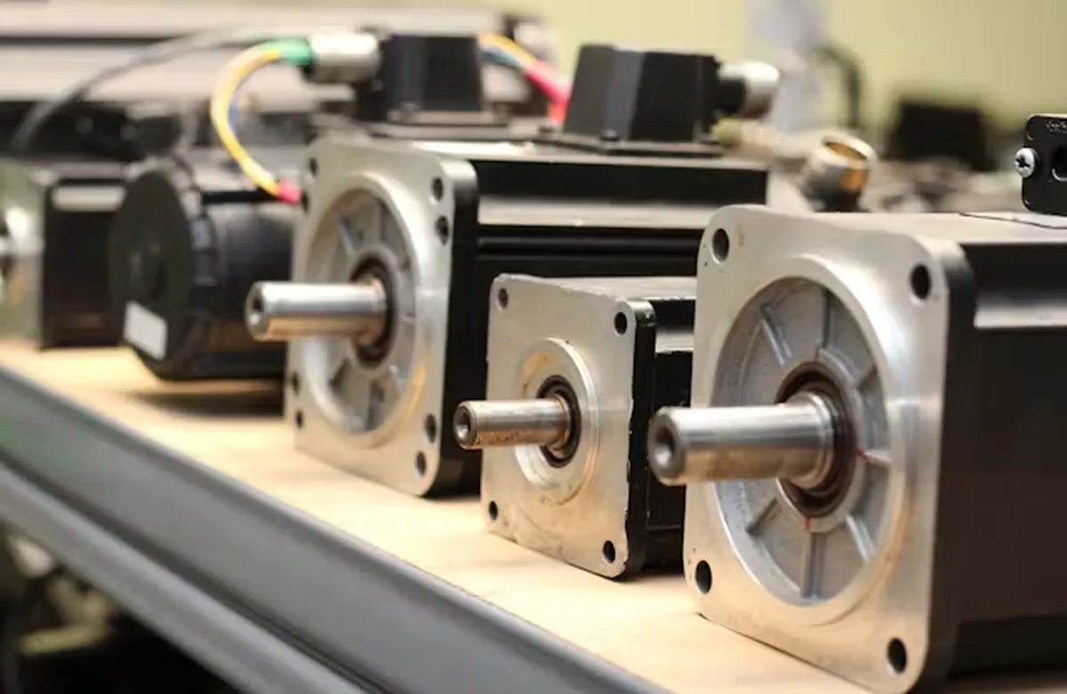
- Precision Equipment: In devices requiring accurate torque transmission, such as encoders, stepper motors, or servo systems, Oldham couplings provide a reliable connection while minimizing backlash and maintaining positional accuracy.
- Industrial Automation: They’re common in conveyor systems, robotics, and assembly lines, where consistent power transfer is needed despite minor shaft offsets due to wear, thermal expansion, or design tolerances.
- Printing and Packaging Machines: These couplings help maintain smooth operation in rollers and drive systems, ensuring consistent performance even if components shift slightly over time.
- Medical Devices: In equipment like imaging machines or surgical tools, Oldham couplings are valued for their ability to handle misalignment quietly and with low vibration, which is critical for precision and patient safety.
- Aerospace and Defense: They’re used in lightweight, high-reliability systems—think actuators or control mechanisms—where misalignment might occur due to structural flexing or environmental stress.
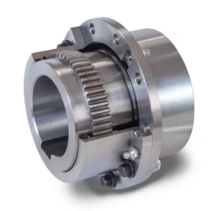
Oldham Couplings vs. Flexible Spider Couplings
Oldham couplings and flexible spider couplings are both used to connect rotating shafts, but they differ in design and application. Oldham couplings feature two hubs with a central disc that slides between them, accommodating misalignment (especially parallel) while transmitting torque. They’re rigid torsionally, ideal for precise motion control, and often used in machinery like pumps or encoders. However, they have limited flexibility and can wear under high angular misalignment.
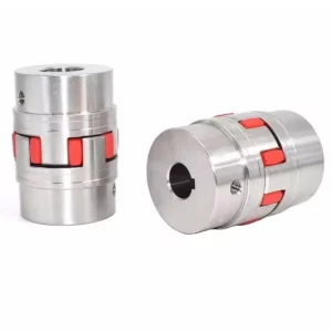
Flexible spider couplings, also called jaw couplings, consist of two hubs with interlocking jaws and a flexible elastomeric "spider" insert. This spider absorbs shock, dampens vibration, and handles moderate angular, parallel, and axial misalignment. They’re simpler, cost-effective, and widely used in motors, conveyors, and general-purpose equipment. While less precise than Oldham couplings, they excel in dynamic, high-vibration environments due to their resilience and damping properties.
| Feature | Oldham Couplings | Flexible Spider Couplings |
|---|---|---|
| Design Structure | Consists of two hubs and a central disc (slider) with perpendicular slots | Consists of two hubs with a flexible elastomeric element (spider) in between |
| Primary Function | Transmits torque while accommodating parallel misalignment | Transmits torque while absorbing misalignment and vibration |
| Misalignment Handling | Excellent for parallel (lateral) misalignment, limited angular misalignment | Handles angular, parallel, and axial misalignment effectively |
| Torque Capacity | Moderate torque capacity, depends on material and size | Higher torque capacity due to robust spider design |
| Vibration Damping | Minimal vibration damping due to rigid components | Excellent vibration damping due to flexible spider element |
| Backlash | Zero backlash when properly designed | Minimal backlash, depends on spider material and fit |
| Material Options | Hubs typically made of aluminum or steel; disc can be plastic or metal | Hubs often steel or aluminum; spider made of rubber, polyurethane, etc. |
| Flexibility | Less flexible, primarily designed for parallel offset | Highly flexible due to elastomeric spider |
| Wear Resistance | Disc may wear over time, especially with high misalignment | Spider may wear out but is replaceable; hubs are durable |
| Maintenance | Requires periodic inspection of disc for wear | Spider element may need replacement over time |
| Operating Speed | Suitable for moderate speeds; high speeds may cause disc wear | Suitable for higher speeds due to balanced design and damping |
| Cost | Generally lower cost due to simpler design | Slightly higher cost due to flexible element and manufacturing |
| Temperature Range | Limited by disc material (e.g., plastic discs have lower temperature tolerance) | Wider range, depending on spider material (e.g., polyurethane vs. rubber) |
| Applications | Used in precision equipment, encoders, and light-duty machinery | Common in pumps, motors, and industrial machinery with vibration |
| Installation Ease | Relatively easy to install, but alignment precision is critical | Easy to install, more forgiving of minor misalignments |
| Noise Reduction | Minimal noise reduction due to rigid construction | Reduces noise effectively due to damping properties of the spider |
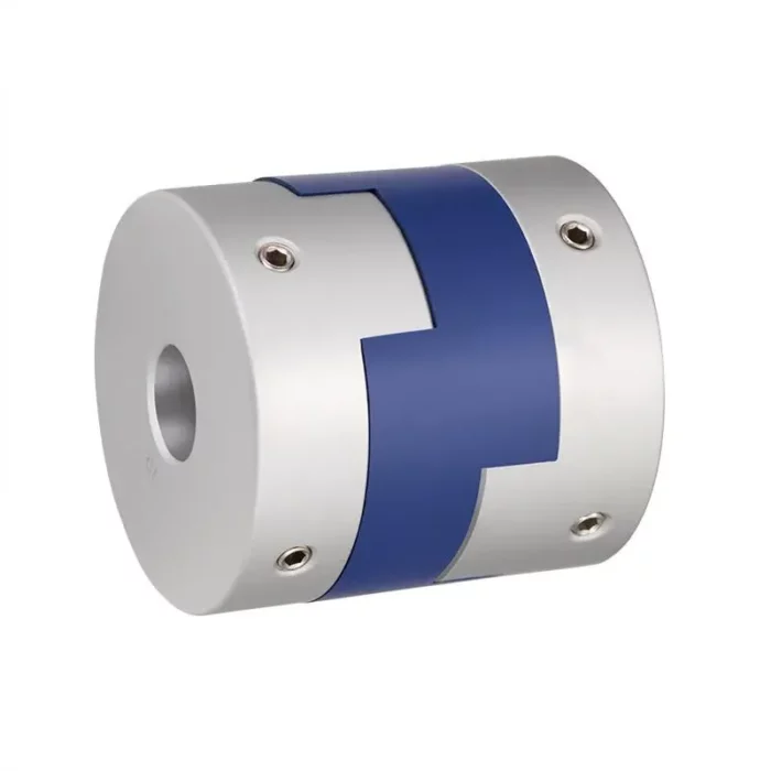 | 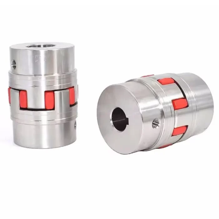 |
| Oldham Couplings | Flexible Spider Couplings |
Additional information
| Edited by | Yjx |
|---|