RE72058 Hydraulic Gear Pump for John Deere Tractor 5410, 5415, 5420, 5510, 5615, 5715, 5076E, 5082E, 5083E, 5090E, 5093E, 5101E
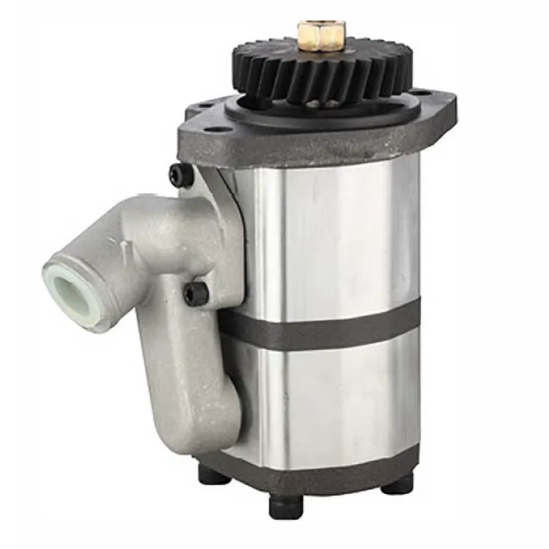
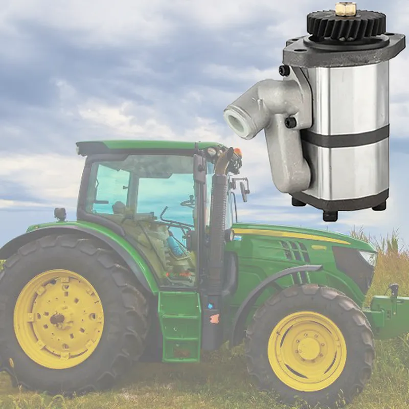
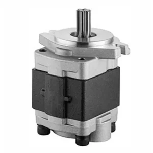
The RE72058 Hydraulic Gear Pump is a high-performance replacement part designed for various John Deere tractor models, including the 5410, 5415, 5420, 5510, 5615, 5715, 5076E, 5082E, 5083E, 5090E, 5093E, and 5101E. This double gear pump delivers hydraulic fluid under pressure to power critical tractor functions like steering, lifting, and implement operation. The tractor hydraulic pump design ensures a steady flow rate, reduced maintenance requirements, and a longer service life.
The RE72058 Hydraulic Gear Pump is a high-performance replacement part designed for various John Deere tractor models, including the 5410, 5415, 5420, 5510, 5615, 5715, 5076E, 5082E, 5083E, 5090E, 5093E, and 5101E. This double gear pump delivers hydraulic fluid under pressure to power critical tractor functions like steering, lifting, and implement operation. The tractor hydraulic pump design ensures a steady flow rate, reduced maintenance requirements, and a longer service life.
RE72058 Hydraulic Gear Pump Specifications
Direct fit for the following equipment: John Deere Series 5000: 5076E, 5076EL, 5076EF, 5082E, 5083E, 5090E, 5090EL, 5090EH, 5093E
John Deere Series 5001: 5101E
John Deere Series 5003: 5403, 5603
John Deere Series 5005: 5605, 5705
John Deere Series 5010: 5410, 5510, 5510N
John Deere Series 5015: 5415, 5415H, 5515, 5515F, 5515V, 5615, 5615F, 5615V, 5715, 5715HC
John Deere Series 5020: 5420, 5420N, 5520, 5520N
John Deere Series 5025: 5425, 5425N, 5625, 5725, 5725N
Hydraulic Gear Pump Replacement for John Deere RE72058
| Applied to: | John Deere Tractor |
| OEM Ref.No.: | RE73947, RE72058, RE69866 |
| Nominal Displacement: | 30/14ml/r |
| Maximum Pressure· | 250bar |
| Rotational Speed: | 700-2500r/min |
| Fuel Feed Hole: | Φ32 |
| Fuel Discharge Hole: | M27*2 & M22*1.5 |
| Direction of Rotation: | Left (Anti-clockwise) |

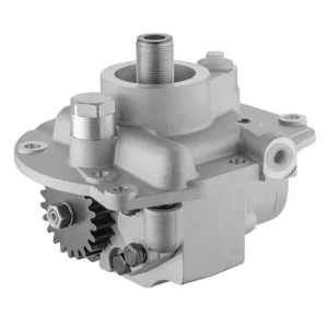
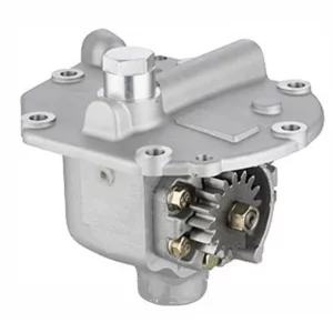
Components of Hydraulic Gear Pump for Tractor
- Gear Set
The core components of a hydraulic gear pump consist of a pair of meshing gears, a driving gear and a driven gear. These gears rotate to generate suction, drawing hydraulic oil into the pump and discharging it under pressure, thereby driving the hydraulic system. - Pump Casing
The tractor hydraulic pump casing wraps around and protects the internal components, including the gear set and bearings. It is usually made of high-strength materials such as cast iron or aluminium to withstand high pressure and prevent oil leakage, ensuring durability and efficiency. - Oil Inlet and Outlet Ports
The oil inlet allows hydraulic oil to enter the tractor hydraulic gear pump, while the oil outlet guides the pressurized oil to the hydraulic system of the tractor. The design of these oil ports is intended to support high-pressure oil flow, and their dimensions have been precisely adjusted to ensure the optimal flow of the oil. - Drive Shaft
The drive shaft connects the hydraulic pump to the engine or transmission system of the tractor. When the engine is running, it rotates the drive shaft, which in turn drives the gear set and causes the hydraulic pump for tractor to generate hydraulic pressure. - Bearings and Seals
Bearings support rotating parts, reducing friction and wear during operation. Seals can prevent hydraulic oil from leaking from the pump and stop contaminants from entering, ensuring that the system operates efficiently and is protected from damage caused by dust or debris. - Pressure Relief Valve
The pressure relief valve is a safety device integrated in the hydraulic system, used to protect tractor hydraulic pumps and other components from overpressure damage. When the pressure exceeds the safe working limit, it will automatically release the excess hydraulic oil to prevent system damage.
How to Install Hydraulic Pump on Tractor
- Prepare the Tractor and Working Area
Park the tractor on a flat and stable road surface and turn off the engine. Operate all hydraulic control devices to release the residual pressure and ensure that the hydraulic system has been depressified. Prepare the necessary tools for installation, replacement pumps and safety equipment. - Disassemble the Old Hydraulic Pump
Disconnect the hydraulic pipeline of the existing pump to ensure that the leaked liquid is collected into the container to prevent overflow. Unscrew the bolts of the hydraulic pump in tractor from the mounting bracket, carefully remove it, and check if there are any damaged or worn connectors that need to be replaced. - Inspect and Clean the Components
Before installing the new tractor hydraulic pump, please check whether the hydraulic pipelines, connectors and installation brackets are dirty, damaged or worn. Thoroughly clean all components, remove debris or contaminants that may interfere with the operation of the pump, and replace damaged parts if necessary. - Install a New Pump
Install the new hydraulic gear pump onto the mounting bracket and evenly tighten the bolts to the torque recommended by the manufacturer for fixation. Make sure the pump is correctly aligned to avoid pulling the drive shaft and other connecting components during operation. - Reconnect the Hydraulic Pipeline and the Drive Shaft
Reconnect the hydraulic pipeline to the inlet and outlet of the pump, ensuring a firm connection and no leakage. Reconnect the drive shaft to align it correctly with the tractor hydraulic gear pump. Tighten all the connecting parts and avoid over-tightening to prevent damage to the threads or joints. - Test the Hydraulic System
Fill the hydraulic oil tank to the recommended level, and then start the tractor engine to test the new hydraulic pump for tractor. Operate the hydraulic control device and check whether the pressure and functions are normal. Check for any leakage or abnormal noise and solve the problem in time before the tractor returns to normal use.

Additional information
| Edited by | Yjx |
|---|
Related products
-
D8NN600AC Hydraulic Gear Pump for Ford Tractor 5110, 5610, 6410, 6610, 6710, 6810, 7010, 7410, 7610, 7710, 7810, 7910, 8010, 8210
-
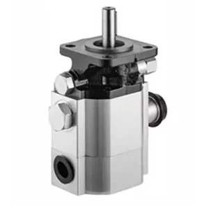
CBNA-8.8/3.6 Log Splitter Hydraulic Pump 2 Stage Log Splitter Pumps
-

2CB-E8.8/1.8 Log Splitter Hydraulic Pump 2 Stage Log Splitter Pumps
-
CPC30.5.18 Forklift Hydraulic Pumps
-
D8NN600LB Hydraulic Gear Pump for Ford Tractor 2810, 2910, 3230, 3400, 3420, 3430, 3610, 3900, 3910, 3930, 4100, 4110, 4130, 4600, 4610, 4630, 4830, 5030