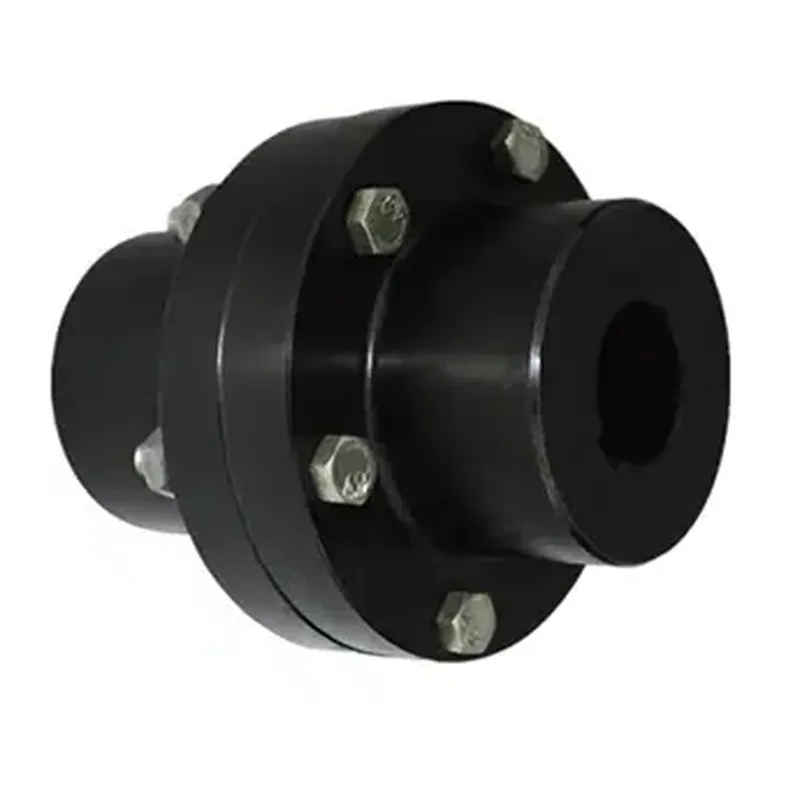
Rigid Couplings
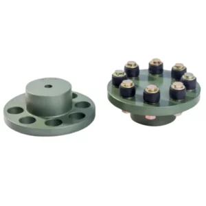
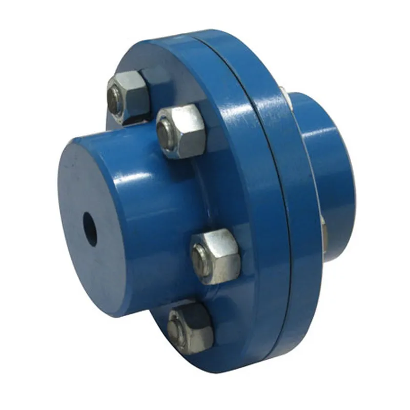
Rigid Couplings (RM Couplings) with taper bore bushes provide users with a quick and easy fixing of rigidly connecting shafts with the convience of a wide selection of shaft sizes of the Taper Bore bushes. The male flange can have the bush installed from the Hub side (H) or from Flange side (F). The female always has the bush fitting F which gives two possible coupling assembly types HF and FF. When using on horizontal shafts, select the most convenient assembly.
Rigid Couplings (RM Couplings) with taper bore bushes provide users with a quick and easy fixing of rigidly connecting shafts with the convenience of a wide selection of shaft sizes of the Taper Bore bushes. The male flange can have the bush installed from the Hub side (H) or from the Flange side (F). The female always has the bush fitting F which gives two possible coupling assembly types HF and FF. When using horizontal shafts, select the most convenient assembly.
Rigid Coupling Size Chart
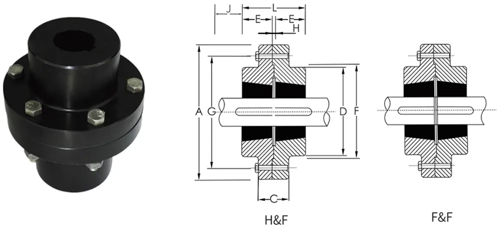
Size | Bush NO. | Max Bore | A | C | D | E | F nom | G nom | H | J | L | |
Metric | Inch | |||||||||||
RM12 | 1210 | 32 | 1 1/4" | 118 | 35 | 83 | 26 | 76 | 102 | 7 | 38 | 57 |
RM16 | 1615 | 42 | 1 1/2" | 127 | 43 | 80 | 38 | 89 | 105 | 7 | 38 | 83 |
RM25 | 2517 | 60 | 2 1/2" | 178 | 51 | 123 | 45 | 127 | 149 | 7 | 48 | 97 |
RM30 | 3030 | 75 | 3" | 216 | 65 | 145 | 76 | 152 | 181 | 7 | 54 | 159 |
RM35 | 3535 | 90 | 3 1/2" | 248 | 75 | 178 | 89 | 178 | 213 | 7 | 67 | 185 |
RM40 | 4040 | 100 | 4" | 298 | 76 | 210 | 102 | 216 | 257 | 7 | 79 | 210 |
RM45 | 4545 | 110 | 41/2" | 330 | 86 | 230 | 114 | 241 | 286 | 7 | 89 | 235 |
RM50 | 5050 | 125 | 5" | 362 | 92 | 260 | 127 | 267 | 314 | 7 | 92 | 260 |
Advantages of the Rigid Couplings
Rigid couplings are mechanical devices used to connect two shafts together to transmit power and torque in a system where precise alignment is critical. Here are the key advantages of rigid couplings:
- High Torque Transmission: Rigid couplings provide a solid, inflexible connection between shafts, allowing for efficient and reliable transmission of high torque without slippage or loss of power.
- Precision and Alignment: They maintain precise shaft alignment, which is essential in applications where misalignment could lead to vibration, wear, or system failure. This makes them ideal for machinery requiring exact positioning.
- Simple Design and Cost-Effectiveness: With no moving parts, rigid couplings are straightforward in design, easy to install, and typically more affordable than flexible alternatives. Their simplicity also reduces maintenance needs.
- Durability: Made from robust materials like steel or aluminum, rigid couplings are highly durable and resistant to wear, making them suitable for heavy-duty applications.
- No Backlash: Unlike flexible couplings, rigid couplings have zero backlash (play between components), ensuring accurate motion transfer, which is critical in precision equipment like CNC machines or robotics.
- Compact Size: Their compact design allows them to fit in tight spaces, making them practical for systems with limited room for components.
- Reliability in Stable Conditions: In systems where shafts are already well-aligned and operating conditions are stable (e.g., no thermal expansion or dynamic loads), rigid couplings offer consistent, dependable performance.
Rigid Coupling Applications
Rigid couplings are mechanical devices used to connect two shafts in a system, ensuring they rotate together at the same speed and torque without any relative motion or flexibility between them. They are typically employed in applications where precise alignment and a strong, inflexible connection are critical. Here are some common applications:
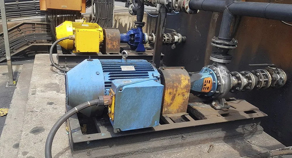
- Power Transmission in Machinery: Rigid couplings are widely used in industrial machinery, such as pumps, compressors, and conveyors, where shafts need to transmit power efficiently without slippage or misalignment. For example, in a pump system, a rigid coupling ensures the motor shaft and pump shaft operate as a single unit.
- Precision Equipment: In applications requiring high accuracy, like CNC machines, lathes, or milling machines, rigid couplings maintain exact shaft alignment, minimizing vibration and ensuring consistent performance during cutting or shaping processes.
- Electric Motors and Generators: Rigid couplings connect motor shafts to driven equipment in systems where flexibility isn’t needed, such as small electric generators or fans, providing a direct and reliable power transfer.
- Heavy Duty Industrial Systems: In steel mills, mining equipment, or large mixers, rigid couplings handle high torque loads, connecting massive shafts that drive heavy components. Their durability and simplicity make them ideal for such rugged environments.
- Automotive and Aerospace Testing: Rigid couplings are used in test rigs or dynamometers to simulate real-world conditions, linking the test shaft to the load or measurement device with no play or deflection.
- Piping Systems (Non-Shaft Applications): Outside of rotating machinery, rigid couplings can also refer to pipe fittings that join two pipes end-to-end without flexibility, commonly seen in plumbing or oil and gas pipelines where a fixed, leak-proof connection is required.
How to Choose the Right Rigid Coupling for Your Need
Choosing the right rigid coupling depends on your specific application and requirements. Rigid couplings are used to connect two shafts in a power transmission system, ensuring precise alignment and efficient torque transfer without flexibility. Here are some tips to help you select the appropriate rigid coupling:
- Determine Shaft Size and Compatibility: Measure the diameter of both shafts to ensure the coupling’s bore size matches precisely. Accurate sizing prevents slippage and ensures efficient torque transmission. Check for keyways or other shaft features that may require specific coupling designs to accommodate them properly.
- Assess Torque Requirements: Evaluate the torque load the coupling must handle, including peak and continuous torque. Select a coupling with a torque rating that exceeds the application’s maximum demand to avoid failure under stress and ensure long-term reliability.
- Consider Misalignment Tolerance: Although rigid couplings don’t accommodate misalignment, verify that your system’s shafts are perfectly aligned. Even slight misalignment can cause stress, vibration, or premature wear, so ensure precise alignment during installation to maximize coupling performance.
- Evaluate Material Selection: Choose a coupling material based on the operating environment. Steel offers high strength for heavy-duty applications, while aluminum is lightweight for lower torque needs. Stainless steel resists corrosion in harsh conditions, ensuring durability.
- Check Operating Conditions: Analyze environmental factors like temperature, humidity, and exposure to chemicals. Select a coupling designed to withstand these conditions without degrading, such as one with protective coatings or corrosion-resistant materials for extreme environments.
- Confirm Coupling Type: Decide between clamp-style, set-screw, or flanged rigid couplings based on your application. Clamp-style provides easy installation, set-screw offers simplicity, and flanged suits high-torque systems requiring robust connections for heavy machinery.
Additional information
| Edited by | Yjx |
|---|