W Type QD Bushings
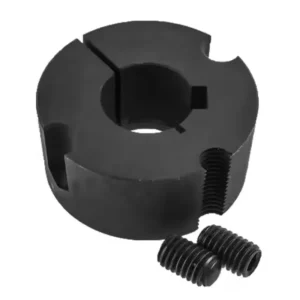
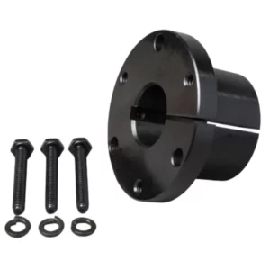
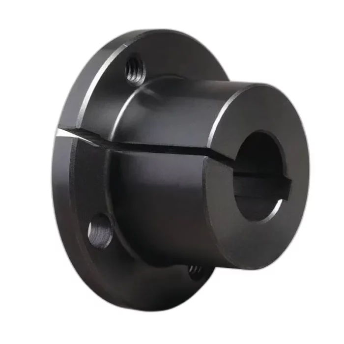
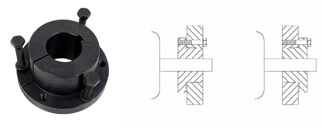
W Type QD (Quick Detachable) bushings are precision-engineered components used to mount pulleys, sprockets, or sheaves onto shafts in power transmission systems. Featuring a flanged design with a 4-degree taper and a split through the flange, they ensure easy installation and removal. Tightening cap screws secures the bushing, providing a tight press fit on the shaft. Typically made of steel or ductile iron, W Type QD bushings offer high torque capacity and are ideal for heavy-duty applications requiring frequent component changes. Their robust construction enhances clamping force, ensuring reliable performance in industrial settings like conveyors and machinery.
W Type QD (Quick Detachable) bushings are precision-engineered components used to mount pulleys, sprockets, or sheaves onto shafts in power transmission systems. Featuring a flanged design with a 4-degree taper and a split through the flange, they ensure easy installation and removal. Tightening cap screws secures the bushing, providing a tight press fit on the shaft. Typically made of steel or ductile iron, W Type QD bushings offer high torque capacity and are ideal for heavy-duty applications requiring frequent component changes. Their robust construction enhances clamping force, ensuring reliable performance in industrial settings like conveyors and machinery.
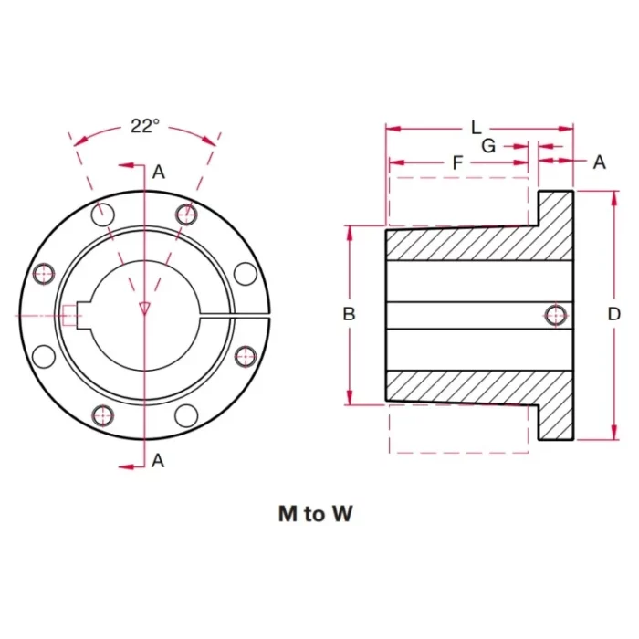
W Type QD Bushing Dimensions
 |  |
| QD Bushing Type: | W | |
| Dimensions(in): | A | 2 |
| B | 10.437 | |
| D | 15 | |
| E | 9-3/8 | |
| F | 9 | |
| G | 1/2 | |
| L | 11-3/8 | |
| Bolt Circle (in): | 12-3/4 | |
| Stock Bore Range(in): | Min. | 4 |
| Max. | Standard Keyway 7-1/2 Shallow Keyway 8-1/2 No Keyway - | |
| Cap Screws Included: | No. | 4 |
| Thread | 1-1/8-11.5 | |
| Length (in) | 11-1/2 | |
| Set Screw Size: | 1 | |
| Wrench-Torque (in-Ibs): | 7,200 | |
| Approx.Weight (Ibs): | 250.0 | |
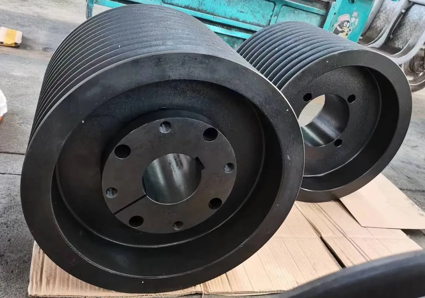
Applications of W Type QD Bushings
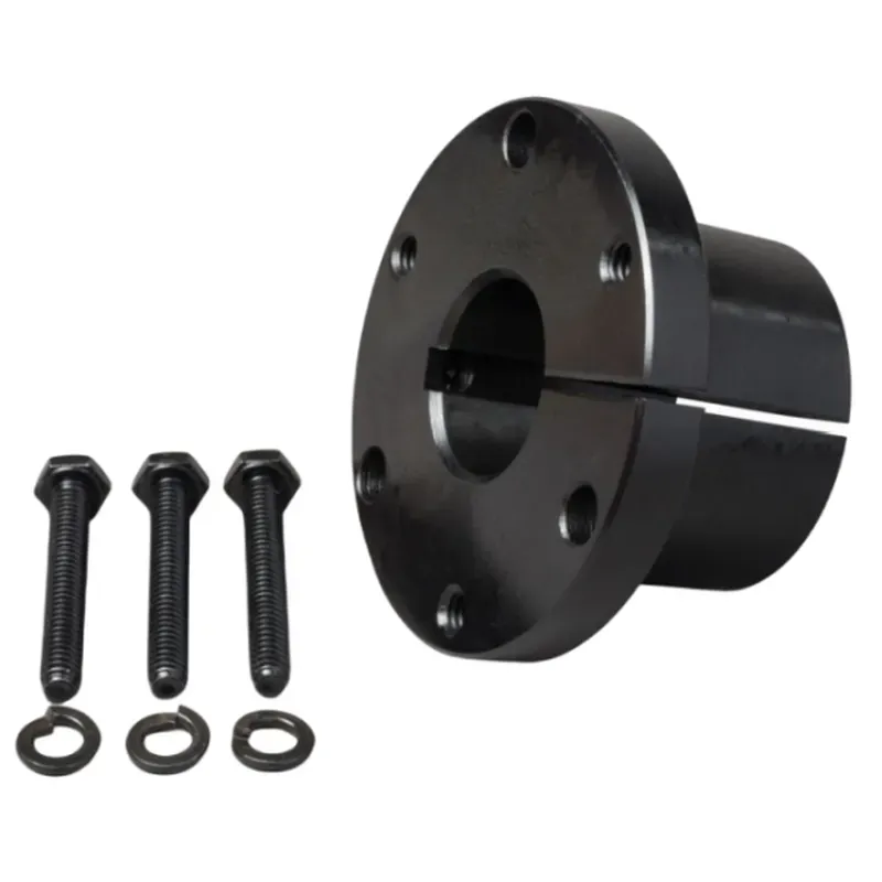
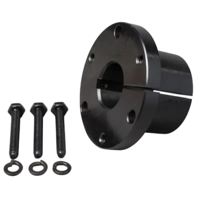
W Type QD (Quick Detachable) bushings are robust, large-diameter bushings designed for heavy-duty power transmission applications requiring high torque and secure shaft mounting. They feature a split, tapered design with a flange for easy installation and removal, providing strong clamping force. Here are their primary applications:
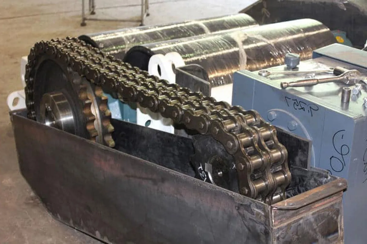
- Heavy-Duty Conveyor Systems: W Type QD bushings are used in large-scale conveyor systems for mining, quarrying, and material handling. Their high torque capacity (up to 7,200 pounds) ensures secure mounting of pulleys and sprockets, facilitating reliable power transmission under demanding conditions.
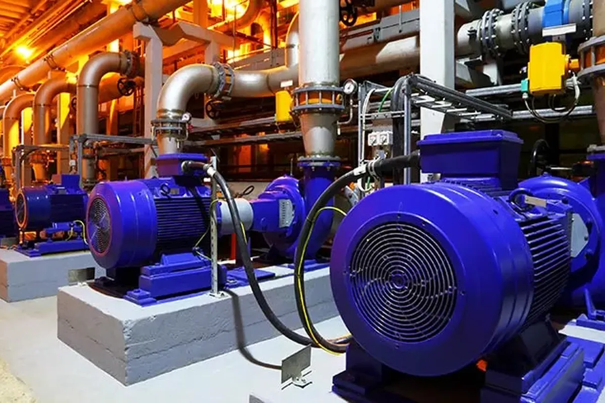
- Industrial Pulley Drives: These bushings are employed in industrial pulley drives for manufacturing and processing plants. Their split flange and 4-degree taper design allow easy installation and removal, reducing downtime during maintenance of V-belt or synchronous belt systems.
- Large-Scale Agricultural Equipment: W QD bushings are critical in agricultural machinery like combine harvesters and grain elevators. Their durable ductile iron construction withstands high loads, ensuring efficient power transfer in harsh, dusty environments with frequent component adjustments.
- Marine Propulsion Systems: In marine applications, W Type QD bushings secure pulleys and gears in propulsion systems. Their corrosion-resistant materials and easy detachment feature support quick repairs in marine environments, minimizing vessel downtime during critical operations.
- Heavy Machinery in Construction: QD bushings are integral to construction equipment like cranes and excavators. Their ability to handle high torque and resist slippage ensures stable power transmission, enhancing safety and efficiency on construction sites.
- Power Transmission in Food Processing: In food processing plants, these bushings mount sprockets and pulleys in conveyor and packaging systems. Their ease of installation and removal supports frequent cleaning and component changes to meet hygiene standards.
 |  |
 |  |
W Type QD Bushing Installation and Removal
Install QD Bushing
(1) Thoroughly clean the shaft, bushing bore, outside of the bushing, and the sprocket/sheave hub bore to remove any oil, paint, or dirt. Additionally, ensure to file away any burrs.
(2) To assemble the sprocket/sheave and bushing, begin by sliding the sprocket/sheave onto the tapered bushing surface, ensuring proper alignment. Align the unthreaded holes in the sprocket/sheave hub with the threaded holes in the flange of the bushing. Proceed to hand-tighten the cap screws with lock washers installed. Then, mount the sprocket/sheave and bushing assembly onto the shaft, positioning the bushing flange either inward or outward based on your configuration requirements. Some assemblies allow for a reverse mount, with the bushing flange facing outward while still facilitating cap screw installation from the outside of the assembly.
(3) With the key resting in the shaft keyway, position the assembly onto the shaft, allowing for slight axial movement of the sprocket/sheave, which may occur during the tightening process. Alternatively, for installing large or heavy parts in a conventional mount, it might be easier to mount the key and bushing on the shaft first. Then, place the sprocket/sheave on the bushing and align the holes accordingly.
(4) Alternatively, tighten the cap screws in sequence until the sprocket/sheave and bushing tapers are fully seated together. Apply approximately half of the recommended bolt torque as specified in Table 2.
| Bolts (in) | Torque Wrench | |||
|---|---|---|---|---|
| Qty. | Size | lb-ft | lb-in | |
| H | 2 | 1/4×3/4 | 7.9 | 95 |
| JA | 3 | 10-24×1 | 4.5 | 54 |
| SH & SDS | 3 | 1/4-20×1 3/8 | 9.0 | 108 |
| SD | 3 | 1/4-20×1 7/8 | 9.0 | 108 |
| SK | 3 | 5/16-18×2 | 15.0 | 180 |
| SF | 3 | 3/8-16×2 | 30.0 | 360 |
| E | 3 | 1/2-13×2 3/4 | 60.0 | 720 |
| F | 3 | 9/16-12×3 5/8 | 75.0 | 900 |
| J | 4 | 5/8-11×4 1/2 | 135.0 | 1620 |
| M | 4 | 3/4-10×6 3/4 | 225.0 | 2700 |
| N | 4 | 7/8-9×8 | 300.0 | 3600 |
| P | 4 | 1-8×9 1/2 | 450.0 | 5400 |
| W | 4 | 1 1/8-7×11 1/2 | 600.0 | 7200 |
| S | 5 | 1 1/4-7×15 1/2 | 750.0 | 9000 |
(5) Inspect the alignment and axial runout (wobble) of the sprocket/sheave, and make adjustments as needed to ensure proper alignment.
(6) Continue alternating the tightening of the cap screws until reaching the recommended torque values specified in Table 2 below. Do not exceed the recommended torque once reached.
Note: Excessive bolt torque can lead to sprocket/sheave and/or bushing breakage. When properly mounted, there should be a gap between the bushing flange and the sprocket/sheave.
(7) When available, tighten the set screw to securely hold the key in place during operation.
Remove QD Bushing
(1) Loosen and remove all mounting bolts.
(2) Insert cap screws into all threaded jack screw holes.
(3) Loosen the bushing by first tightening the screw furthest from the bushing saw slot, then, alternately tighten the remaining screws. Keep tightening the screws in small but equal increments until the tapered sprocket/sheave and bushing disengage.
Note: Excessive or unequal pressure on the bolts can break the bushing flange, making removal impossible without destroying the sprocket/sheave.
Additional information
| Edited by | Yjx |
|---|