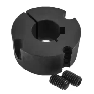
Taper Lock Bushings
Taper-lock bushings represent a widely adopted solution for mounting mechanical transmission components such as sprockets, pulleys, and couplings onto drive shafts. Their efficacy in fastening is attributed to a flanged, split design characterized by a tapered diameter. This design facilitates a secure connection with the shaft by exerting radial pressure, ensuring a tight fit. Notably, taper-lock bushings offer streamlined installation and removal processes devoid of keys or set screws, enhancing operational efficiency.
Taper Lock Bushing Dimension


| Bushing Number | Dimensions(in) | Bolt Circle | Installation Screws (UNC) | Stock Bore Range(in) | G | Wrench Torque (in-lbs) | Torque Application Capacity (in-lbs) | Approx. Weight (lbs) | ||||
|---|---|---|---|---|---|---|---|---|---|---|---|---|
| A | B | Thread Dia. (in) | Length (in) | Min. | Max. | |||||||
| Standard Keyway | Shallow Keyway | |||||||||||
| 1008 | 1.386 | 7/8 | 1-21/64 | 1/4 | 1/2 | 1/2 | 7/8 | 1 | – | 55 | 1,200 | 0.2-0.3 |
| 1108 | 1.511 | 7/8 | 1-29/64 | 1/4 | 1/2 | 1/2 | 1 | 1-1/8 | – | 55 | 1,300 | 0.2-0.3 |
| 1210 | 1-7/8 | 1 | 1-3/4 | 3/8 | 5/8 | 1/2 | 1-1/4 | – | – | 175 | 3,600 | 0.4 -0.6 |
| 1215 | 1-7/8 | 1-1/2 | 1-3/4 | 3/8 | 5/8 | 1/2 | 1-1/4 | – | – | 175 | 3,550 | 0.5-0.9 |
| 1310 | 2 | 1 | 1-7/8 | 3/8 | 5/8 | 1/2 | 1-3/8 | – | – | 175 | 3,850 | 0.4-0.7 |
| 1610 | 2-1/4 | 1 | 2-1/8 | 3/8 | 5/8 | 1/2 | 1-1/2 | 1-5/8 | – | 175 | 4,300 | 0.5-0.9 |
| 1615 | 2-1/4 | 1-1/2 | 2-1/8 | 3/8 | 5/8 | 1/2 | 1-1/2 | 1-5/8 | – | 175 | 4,300 | 0.6-1.3 |
| 2012 | 2-3/4 | 1-1/4 | 2-5/8 | 7/16 | 7/8 | 1/2 | 1-7/8 | 2 | – | 280 | 7,150 | 0.9-1.7 |
| 2517 | 3-3/8 | 1-3/4 | 3-1/4 | 1/2 | 1 | 1/2 | 2-1/4 | 2-1/2 | – | 430 | 11,600 | 1.4-3.7 |
| 2525 | 3-3/8 | 2-1/2 | 3-1/4 | 1/2 | 1 | 3/4 | 2-1/4 | 2-1/2 | – | 430 | 11,300 | 2.0-4.9 |
| 3020 | 4-1/4 | 2 | 4 | 5/8 | 1-1/4 | 15/16 | 2-3/4 | 3 | – | 800 | 24,000 | 3.5-6.5 |
| 3030 | 4-1/4 | 3 | 4 | 5/8 | 1-1/4 | 15/16 | 2-3/4 | 3 | – | 800 | 24,000 | 6.4-10.0 |
| 3535 | 5 | 3-1/2 | 4.83 | 1/2 | 1-1/2 | 1-3/16 | 3-1/4 | 3-1/2 | 39° | 1,000 | 44,800 | 10.0-15.2 |
| 4040 | 5-3/4 | 4 | 5.54 | 5/8 | 1-3/4 | 1-7/16 | 3-5/8 | 4 | 40° | 1,700 | 77,300 | 19.5-24.0 |
| 4545 | 6-3/8 | 4-1/2 | 6.13 | 3/4 | 2 | 1-15/16 | 4-1/4 | 4-1/2 | 40° | 2,450 | 110,000 | 12.5-29.9 |
| 5050 | 7 | 5 | 6.72 | 7/8 | 2-1/4 | 2-5/16 | 4-1/2 | 5 | 37° | 3,100 | 126,000 | 20.9-39.0 |
Table 1 – Taper Lock Bushing
What is a Taper Lock Bushing?
Crafted from premium steel or cast materials, our taper lock bushings guarantee efficiency and longevity, our products ensure seamless installation into components without compromising the performance of your system. Trust AGKNX for unparalleled quality and reliability in taper lock bushings.

Applications of Taper Lock Bushings
Taper lock bushings are widely used in mechanical engineering and industrial applications to securely mount components like pulleys, sprockets, and couplings onto shafts. Their design allows for easy installation, removal, and repositioning without damaging the shaft or component, making them a versatile choice in various systems. Here are some key applications:
1. Power Transmission Systems: Taper Lock Bushings are commonly used to attach pulleys or sprockets to shafts in belt or chain drives. This is prevalent in machinery like conveyor systems, HVAC units, and automotive engines, ensuring efficient torque transfer.
2. Industrial Machinery: In equipment such as pumps, fans, and compressors, these bushings provide a reliable connection between the motor shaft and driven components, accommodating slight misalignments and reducing wear.
3. Agricultural Equipment: Tractors, harvesters, and other farm machinery often use Taper Lock Bushings to mount rotating elements, allowing for quick maintenance or replacement in the field.
4. Conveyor Systems: They secure rollers or drive pulleys to shafts, enabling smooth material handling in industries like mining, manufacturing, and logistics.
5. Heavy Duty Applications: In crushers, mills, and gearboxes found in mining or construction, Taper Lock Bushings handle high torque and vibration, maintaining a firm grip under demanding conditions.

Taper Lock Bushing Installation Steps

Figure 1
(7) Continue alternating the tightening of the bolts until reaching the recommended torque values specified in Table 1 above.
Caution: Excessive bolt torque can cause sprocket/sheave and/or bushing breakage.
Note: To ensure proper drive performance, full bushing contact on the shaft is recommended.
(8) To enhance the bushing’s gripping force, firmly tap the face of the bushing using a brass drift or punch. Avoid hitting the bushing directly with the hammer.
(9) Re-torque the bushing bolts after completing Step 8. Once the recommended bolt torque value is reached, do not continue tightening. Over-tightening may lead to over-insertion of the bushing.
(10) After the initial drive run-in, recheck all bolt torque values and periodically thereafter. If any bolts are found to be loose, repeat steps 5 through 9.
(1) Thoroughly clean the shaft, bushing bore, exterior of the bushing, and sprocket/sheave hub bore to remove any traces of oil, paint, or dirt. Additionally, carefully file away any burrs for smooth and precise assembly.
Note: Avoid using lubricants during the installation of tapered bushings to prevent hub fracture.
(2) Insert the bushing into the sprocket/sheave hub and align the holes. All holes should be half-threaded, with installation holes threaded on the sprocket side and removal holes threaded on the bushing side. See Figure 1 below.
(3) Apply a light coating of oil to the bolts and thread them into the half-threaded installation holes, as indicated by the white installation holes in Figure 1.
(4) Position the sprocket/sheave and bushing assembly onto the shaft, ensuring the key rests in the shaft keyway. Allow for slight axial movement of the sprocket/sheave, which may occur during the tightening process.
Note: Avoid lubricating the bushing taper, hub taper, bushing bore, or shaft to prevent the risk of sprocket/sheave hub fracture. DO NOT USE LUBRICANTS.
(5) Alternatively, apply torque to the bushing bolts until the sprocket/sheave and bushing tapers are fully seated together. Use approximately half of the recommended bolt torque (refer to Table 1).
Note: Avoid using worn hex key wrenches, as this may lead to a loose assembly or damage to the bolts.
(6) Inspect the alignment and axial runout (wobble) of the sprocket/sheave, and make adjustments as required for proper alignment.
Taper Lock Bushing Remove Steps

(1) Begin by loosening and removing all mounting bolts.
(2) Insert bolts into all jack screw holes, as indicated by the dark removal holes in Figure 1 above.
(3) Loosen the bushing by alternately tightening the bolts in small, equal increments until the tapered sprocket/sheave and bushing surfaces disengage.
Taper Lock Bushing FAQ
How Does a Taper Lock Bushing Work?
What Materials Are Taper Lock Bushings Made From?
What Are the Benefits of Using a Taper Lock Bushing?
Can Taper Lock Bushings Be Used Without a Keyway?
What Is the Difference Between a Taper Lock and a QD Bushing?
What Maintenance Do Taper Lock Bushings Require?
High Quality Taper Lock Bushing for Sale
-

1008 Taper Lock Bushings
-

1108 Taper Lock Bushings
-

1210 Taper Lock Bushings
-

1215 Taper Lock Bushings
-

1310 Taper Lock Bushings
-

1610 Taper Lock Bushings
-

1615 Taper Lock Bushings
-

2012 Taper Lock Bushings
-

2517 Taper Lock Bushings
-

2525 Taper Lock Bushings
-

3020 Taper Lock Bushings
-

3030 Taper Lock Bushings
-

3535 Taper Lock Bushings
-

4040 Taper Lock Bushings
-

4545 Taper Lock Bushings
-
5050 Taper Lock Bushings