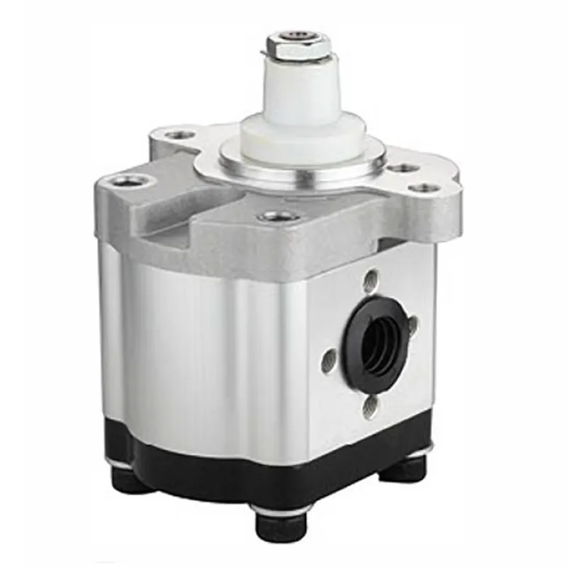
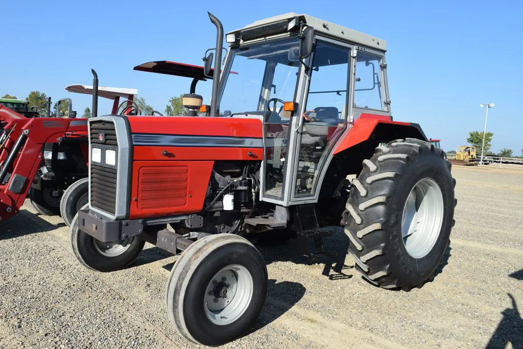
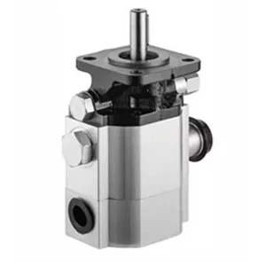
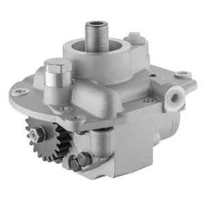
3538958M91 Hydraulic Gear Pump for Massey Ferguson Tractor 373, 373S, 374F, 374S, 377, 383, 383S, 384F, 384S, 387, 393, 393S
The 3538958M91 hydraulic gear pump is an aftermarket replacement part designed for Massey Ferguson tractor models, including the 373, 373S, 374F, 374S, 377, 383, 383S, 384F, 384S, 387, 393, and 393S. This tractor hydraulic pump is responsible for supplying pressurized hydraulic fluid to the tractor’s hydraulic system, enabling the operation of essential functions like lifting, steering, and powering hydraulic implements.
The 3538958M91 hydraulic gear pump is an aftermarket replacement part designed for Massey Ferguson tractor models, including the 373, 373S, 374F, 374S, 377, 383, 383S, 384F, 384S, 387, 393, and 393S. This tractor hydraulic pump is responsible for supplying pressurized hydraulic fluid to the tractor’s hydraulic system, enabling the operation of essential functions like lifting, steering, and powering hydraulic implements.
3538958M91 Hydraulic Gear Pump Specifications
Compatible with Massey Ferguson Tractor(s):
300 Series: 367CF, 373, 373LX, 373S, 374AP, 374APX, 374AQ, 374F, 374FP, 374FPX, 374FQ, 374GE, 374GEX, 374H, 374S, 374SP, 374SP, 374SPX, 374SQ, 374V, 377, 383, 383LX, 383S, 384AP, 384APX, 384AQ, 384F, 384FP, 384FPX, 384FQ, 384GE, 384GEX, 384GE, 384S, 384SP, 384SPX, 384SQ, 384V, 387, 393, 393LX, 393S
F Series: F70, F80, F90
Replacement for Massey Ferguson OEM Number(s): 3533911M91, 3538958M91
| Applied to: | Massey Ferguson Tractor |
| OEM Ref.No.: | 3533911M91, 3538958M91 |
| Nominal Displacement: | 14ml/r |
| Maximum Pressure· | 250bar |
| Rotational Speed: | 500-3000r/min |
| Fuel Feed Hole: | Φ19 |
| Fuel Discharge Hole: | Φ14 |
| Direction of Rotation: | Left (Anti-clockwise) |
Tractor Hydraulic Gear Pump Design Features
- Gear Mechanism for Fluid Flow
The hydraulic gear pump uses a pair of precisely engineered interlocking gears to create a smooth and consistent hydraulic fluid flow. This design ensures efficient fluid displacement, minimal pulsation, and reliable performance for various hydraulic applications. - High-Quality Materials for Durability
Constructed from durable, wear-resistant materials, the tractor hydraulic pump is designed to withstand high pressure, extreme temperatures, and harsh agricultural conditions. These materials minimize wear and tear, ensuring long-term reliability even under continuous heavy-duty usage. - Compact and Lightweight Design
The pump’s compact structure allows for easy integration into the tractor’s hydraulic system without adding excessive weight. This smaller design improves operational efficiency while maintaining the high output required for demanding agricultural tasks. - Optimized Sealing System
Equipped with advanced seals, the tractor hydraulic gear pump prevents fluid leakage and contamination. This sealing system enhances performance by maintaining consistent pressure while protecting internal components from dirt, debris, and environmental damage. - High-Pressure Tolerance
Designed to handle high-pressure hydraulic systems, the tractor hydraulic pumps maintain steady performance under demanding workloads. Its robust design allows it to operate effectively in applications where heavy lifting or powerful hydraulic output is required. - Ease of Maintenance and Replacement
The hydraulic pump for tractor is designed for user convenience, allowing for straightforward installation, inspection, and servicing. Its modular construction simplifies repairs and replacement, ensuring minimal downtime and consistent performance in agricultural operations.

Working Principle of Hydraulic Pump in Tractor
The working principle of a tractor hydraulic gear pump is based on the movement of hydraulic fluid through a mechanical gear assembly to generate pressurized flow. This pressurized fluid powers various hydraulic systems in the tractor, such as lifting implements, operating steering mechanisms, or driving auxiliary functions. The pump operates using two interlocking gears: the drive gear and the driven gear, which are housed inside a tightly sealed casing.
Additional information
| Edited by | Yjx |
|---|
Related products
-

2CB-4.2/1.0 Log Splitter Hydraulic Pump 2 Stage Log Splitter Pumps
-
D0NN600G Hydraulic Gear Pump for Ford Tractor 5000, 5100, 5200, 7000, 7100, 7200
-
F0NN600AA Hydraulic Gear Pump for Ford Tractor 5640, 6640, 7740, 7840, 8240, 8340
-
CBNA-8.8/3.6 Log Splitter Hydraulic Pump 2 Stage Log Splitter Pumps
-
D8NN600AC Hydraulic Gear Pump for Ford Tractor 5110, 5610, 6410, 6610, 6710, 6810, 7010, 7410, 7610, 7710, 7810, 7910, 8010, 8210