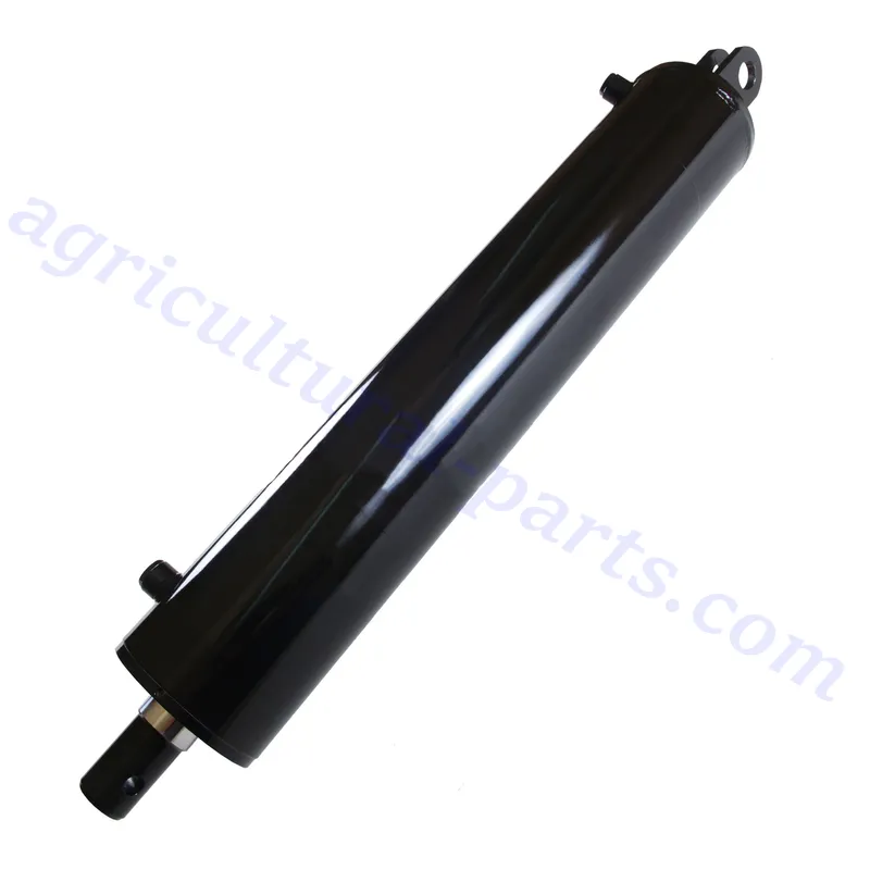
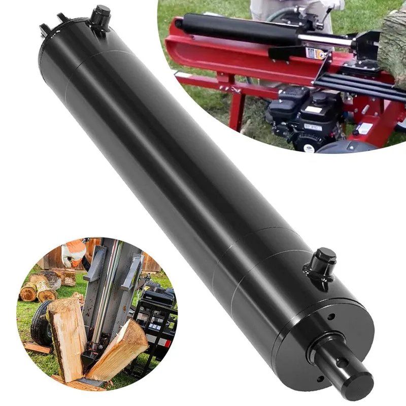
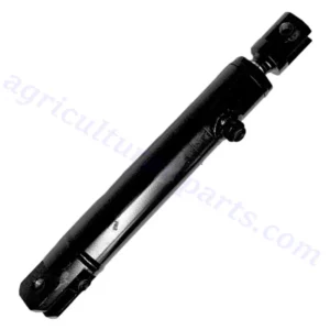
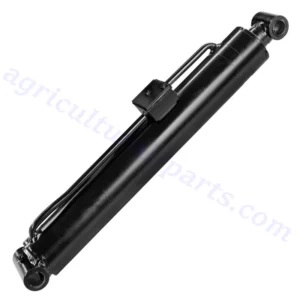
4″ Bore x 24″ Stroke Log Splitter Hydraulic Cylinders
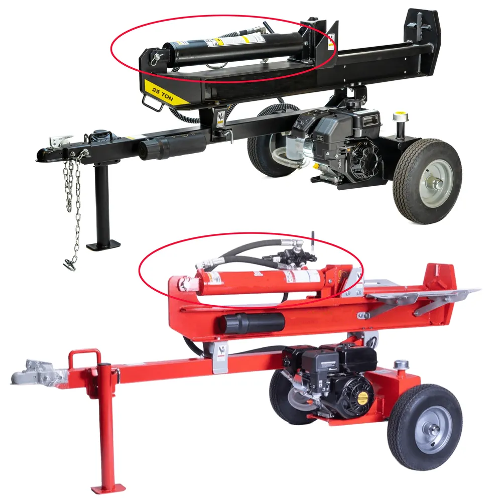
A 4″ bore x 24″ stroke log splitter hydraulic cylinder is a heavy-duty, double-acting hydraulic cylinder component designed for log splitters, capable of handling up to 3500 PSI pressure and a column load of approximately 36,000 lbs. It features a welded steel clevis mount with 1-1/8″ and 9/16″ pinholes for secure attachment, honed cold-drawn tubing, and high-quality polyurethane seals for durability in extreme conditions. Compatible with various log splitters, such as gas log splitters, electric log splitters, 3-point tractor log splitters, and skid steer log splitters. It’s ideal for the replacement of cylinders in brands like Tractor Supply Co., Huskee, SplitMaster, Oregon, SpeeCo, and many others, offering robust performance for splitting tough logs.
A 4" bore x 24" stroke log splitter hydraulic cylinder is a heavy-duty, double-acting hydraulic cylinder component designed for log splitters, capable of handling up to 3500 PSI pressure and a column load of approximately 36,000 lbs. It features a welded steel clevis mount with 1-1/8" and 9/16" pinholes for secure attachment, honed cold-drawn tubing, and high-quality polyurethane seals for durability in extreme conditions. Compatible with various log splitters, such as gas log splitters, electric log splitters, 3-point tractor log splitters, and skid steer log splitters. It’s ideal for the replacement of cylinders in brands like Tractor Supply Co., Huskee, SplitMaster, Oregon, SpeeCo, and many others, offering robust performance for splitting tough logs.
Log Splitter Hydraulic Cylinder Dimensions
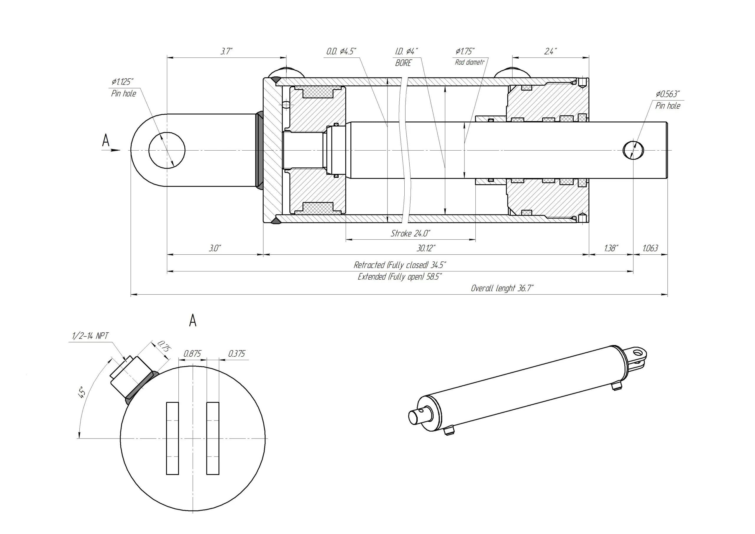
| Bore : | 4 in |
|---|---|
| Outer Dia. (⌀) : | 4.5 in |
| Stroke : | 24 in |
| Rod Dia. (⌀) : | 1.75 in |
| Port Size : | 1/2" NPT |
| Pin Dia. (⌀) : | 9/16 in |
| Extended : | 58.5 in |
| Retracted : | 34.5 in |
| Overall length : | 36.625 in |
| Pressure : | 3500 PSI |
| Column Load : | 36,000 LBs |
| Oil Volume : | 5.22 QTs |
| Design : | Welded |
| Rod Type : | Chrome Plated |
| Rod End : | Pin Hole |
| Action : | Double Acting |
| Weight : | 67 LBs |
Components of Hydraulic Cylinder for Log Splitter
- Cylinder Barrel: The cylinder barrel is the main body of the hydraulic cylinder. It houses the piston and hydraulic fluid, providing a sealed environment for the piston to move within. Made from high-strength steel, the barrel is designed to withstand extreme pressures and wear during operation, ensuring durability and smooth functioning in demanding conditions.
- Piston and Piston Rod: The piston is a cylindrical component inside the barrel that divides it into two chambers. It is attached to the piston rod, which transfers the hydraulic force to the log splitter's wedge. The piston creates pressure differences by sealing off sections of the cylinder, facilitating controlled movement. The rod, made of hardened steel, is engineered to resist bending and corrosion.
- Seals and O-Rings: Seals and O-rings prevent hydraulic fluid from leaking out of the cylinder and ensure proper pressure is maintained. These components are typically made of synthetic rubber or polymers and are designed to endure high temperatures, pressures, and wear over time, ensuring the cylinder operates efficiently without fluid loss.
- End Caps: End caps are attached to both ends of the wood splitter cylinder barrel to seal the system. The rear cap, or base, is stationary, while the front cap has an opening for the piston rod to pass through. These caps also house mounting components, such as threaded holes or clevis mounts, to secure the cylinder in place.
- Hydraulic Ports: Hydraulic ports are entry and exit points for hydraulic fluid within the cylinder. These ports connect to hoses that transfer fluid from the hydraulic pump. The positioning of the ports (inlet and outlet) ensures controlled fluid flow, enabling precise movement of the piston for effective log splitting.
- Mounting Hardware: The mounting hardware includes clevis pins, trunnion mounts, or flanges that secure the hydraulic cylinder to the log splitter's frame. These components ensure stability during operation, allowing the cylinder to handle the high forces generated without shifting or causing damage to the equipment.
Benefits of Hydraulic Log Splitter Cylinders
- High Power Output: Hydraulic cylinders deliver immense force (up to 36,000 lbs) with a 4-inch bore, enabling efficient splitting of dense, tough logs, significantly reducing manual effort and increasing productivity.
- Durability and Longevity: Constructed from honed steel with chrome-plated rods and polyurethane seals, these cylinders resist wear, corrosion, and leaks, ensuring reliable performance over years of heavy-duty log splitting in harsh conditions.
- Versatile Compatibility: Designed for various log splitters (gas, electric, 3-point tractor, or skid steer), these cylinders fit brands like Huskee, SplitMaster, Oregon, SpeeCo, offering flexibility for upgrades or replacements in diverse equipment setups.
- Smooth Operation: The precision-engineered piston and honed barrel ensure smooth, consistent movement, minimizing jams and providing steady force application, which enhances splitting efficiency and reduces operational downtime for users.
- High Pressure Handling: Capable of withstanding pressures up to 3500 PSI, these cylinders maintain performance under extreme loads, ensuring reliable operation even when splitting large or knotty logs, enhancing overall splitting effectiveness.
- Easy Installation: Featuring welded clevis mounts with standard pinholes (1-1/8" and 9/16"), these cylinders allow straightforward attachment to log splitter frames, simplifying setup or replacement and reducing maintenance time for operators.
How to Bleed Hydraulic Cylinder for a Log Splitter?
Bleeding a hydraulic cylinder for a log splitter removes trapped air from the system, ensuring smooth operation and maximum power. Begin by safely positioning the log splitter on a flat surface and turning off the engine or power source to prevent accidental activation. Locate the hydraulic cylinder and reservoir, ensuring the fluid level is adequate (use manual-recommended hydraulic fluid, typically AW-32 or AW-46). Loosen the bleeder valve or screw, usually found near the cylinder’s top or end cap, using a wrench, but do not remove it completely.
Next, slowly cycle the hydraulic log splitter cylinder by manually activating the control valve or lever to extend and retract the piston rod fully, several times. This forces air bubbles to move toward the bleeder valve. As you cycle, watch for air bubbles escaping through the bleeder valve, accompanied by hydraulic fluid. Keep the reservoir topped off to prevent air re-entry. Once only steady fluid (no bubbles) exits the valve, tighten it securely to prevent leaks.
Check the system for proper operation by running the log splitter and observing the cylinder’s movement. If it hesitates or lacks power, repeat the process, as residual air may remain. Always wear safety gear, including gloves and goggles, and consult the splitter’s manual for model-specific instructions. This process, taking about 15–20 minutes, ensures optimal performance, prevents cavitation, and extends the cylinder’s lifespan, maintaining efficient log splitting.
Additional information
| Edited by | Yjx |
|---|
Related products
-
Floating Hydraulic Cylinder for Scissor Type Aerial Work Platforms
-
Leveling Hydraulic Cylinder for Arm Type Aerial Work Platforms
-
Left and Right Forward Extension Hydraulic Cylinder for Forward Moving Forklift
-
Jib Hydraulic Cylinder for Arm Type Aerial Work Platforms
-

Lift Hydraulic Cylinder for Large Tonnage Forklift